128
Operating Instructions – Electronic Motor DRC.-..-SNI
8
Description of power section parameters
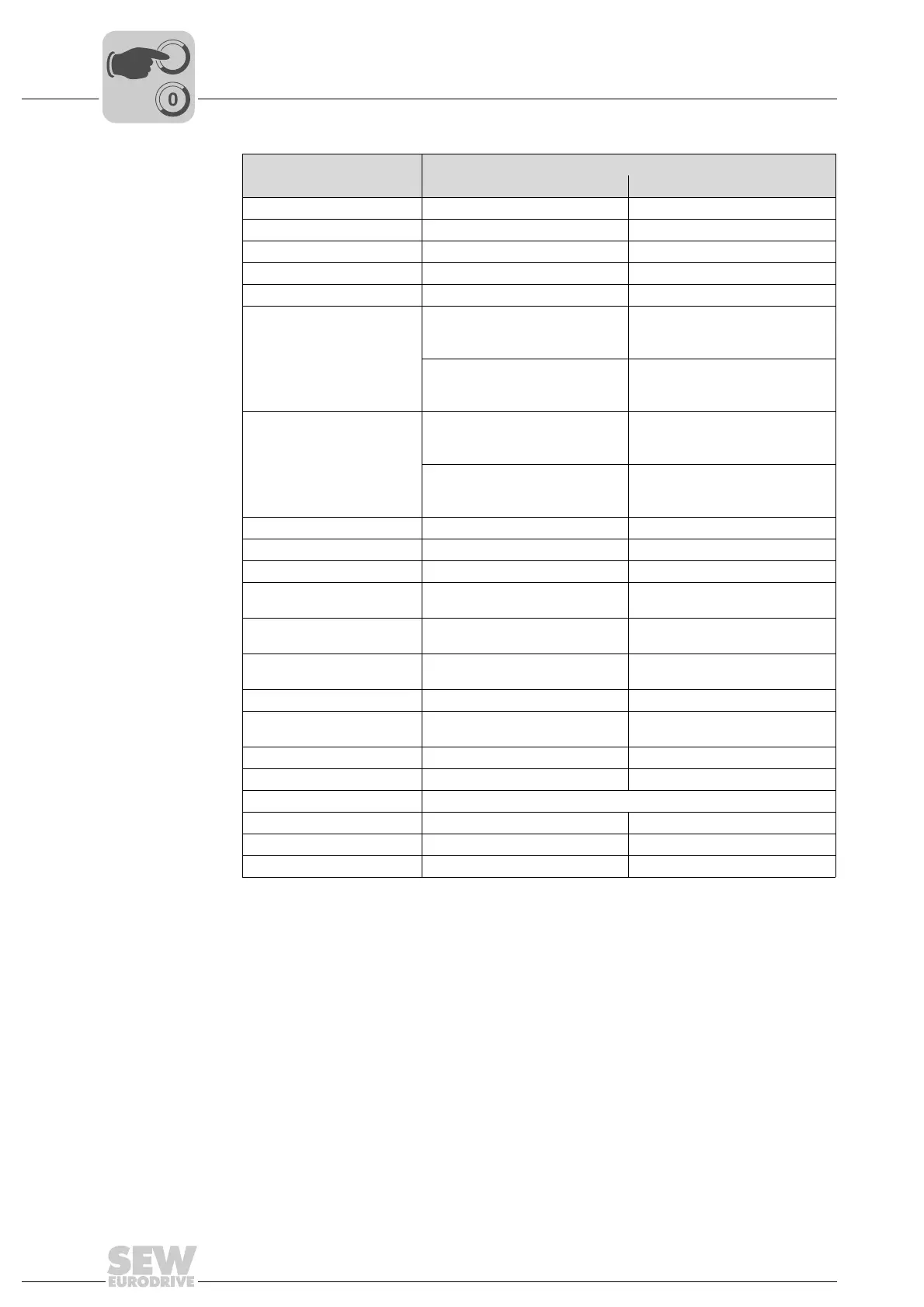
Parameters
Function
Binary output has
"0" signal "1" signal
0 = No function Always "0" signal –
1 = /Fault Collective fault signal –
2 = Ready Not ready Ready for operation
3 = Output stage ON Unit inhibited Unit enabled and motor energized
4 = Rotating field ON No rotating field Rotating field
5 = Brake released
1)
In conjunction with mechatronic
MOVIGEAR
®
drive unit:
DynaStop
®
is activated
In conjunction with mechatronic
MOVIGEAR
®
drive unit:
DynaStop
®
is deactivated
In conjunction with DRC
electronic motor:
Brake applied
In conjunction with DRC
electronic motor:
Brake released
6 = Brake applied
1)
In conjunction with mechatronic
MOVIGEAR
®
drive unit:
DynaStop
®
is deactivated
In conjunction with mechatronic
MOVIGEAR
®
drive unit:
DynaStop
®
is activated
In conjunction with DRC
electronic motor:
Brake released
In conjunction with DRC
electronic motor:
Brake applied
7 = Motor standstill Motor is running Motor is at standstill
8 = Reserved ––
9 = Speed reference signal n > n
ref
(n < n
ref
)n < n
ref
(n > n
ref
)
10 = Speed reference signal
Speed is outside (within) speed
window
Speed is within (outside) speed
window
11 = Setpoint/actual value
comparison signal
n <> n
set
(n = n
set
)n = n
set
(n <> n
set
)
12 = Current reference
signal
I > I
ref
(I < I
ref
)I < I
ref
(I > I
ref
)
13 = Imax signal I < I
max
(I = I
max
)I = I
max
(I < I
max
)
14 = /Warning motor
utilization
100% pre-warning of motor
protection function
–
19 = IPOS in position Position not reached Position reached
20 = IPOS referenced No referencing Referencing finished
21 = IPOS output Depends on IPOS program
22 = /IPOS fault IPOS program error message –
27 = STO – safe torque off Not active Active
34 = Process data bit Bit not set Bit set
1) Controlled by the inverter The "Brake released" and "Brake applied" signals are intended to be passed on
to a master controller.