20
8012707/ZVF9/V2-1/2019-04 | SICKOPERATING INSTRUCTIONS | GM32
Subject to change without notice
3 PREPARING THE GAS DUCT SIDE
Test gas connection (GPP)
CAN line connection: Purge air fixture - SR-unit (see )
Ethernet PC/network connection
Power supply connection
CAN line connection: (see â)
Purge air fixture connection
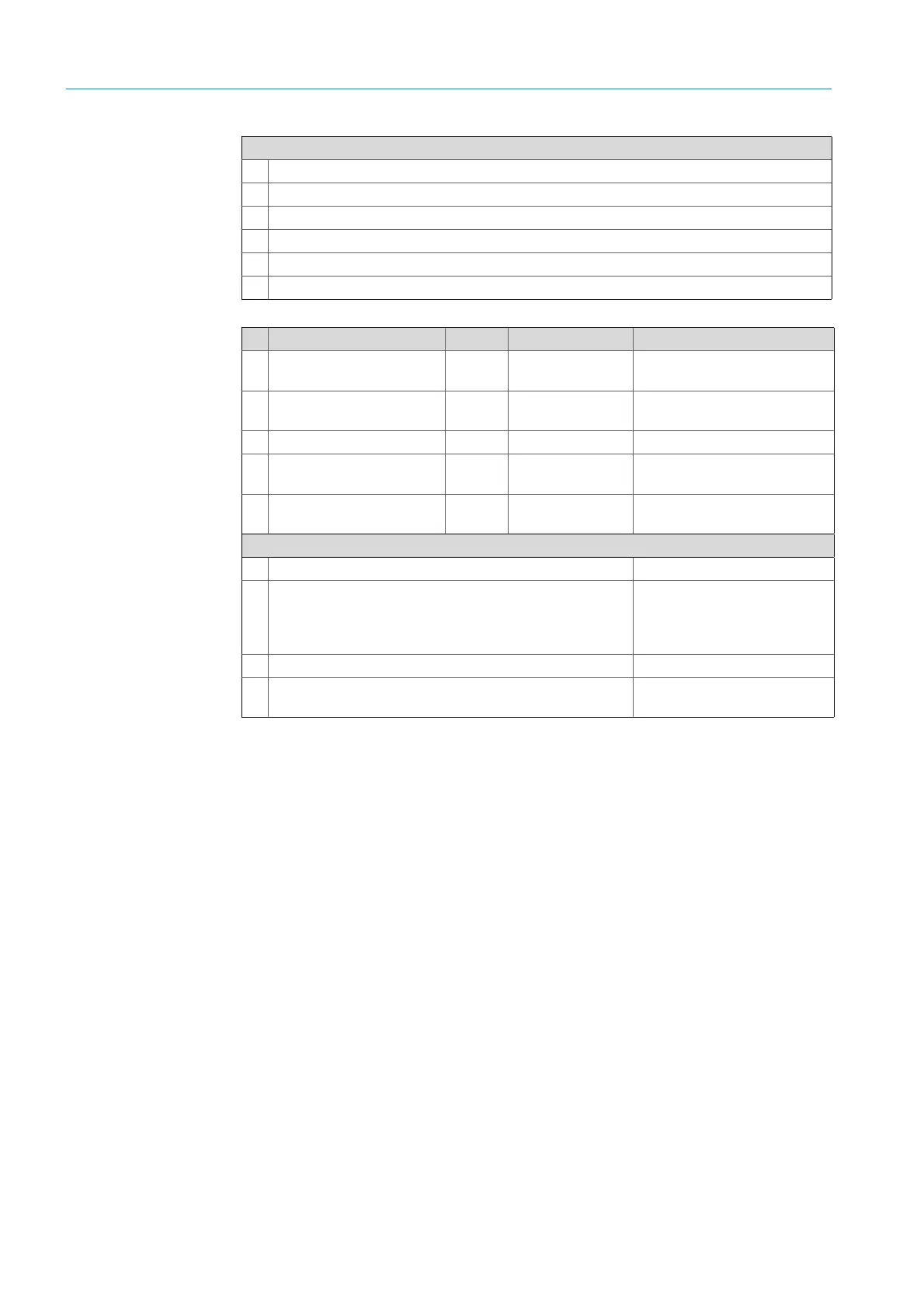
Signal line for connection Length Part number Remark
Purge air fixture - pressure
sensor
à
Purge air fixture -
temperature sensor
á
Filter monitor 5 m 2032143 Included in the purge air fixture
â Power supply SR (standard)
● 10 m
● 20 m
● 2046548
● 2046549
ã
CAN line connection unit -
sender/receiver unit
● 10 m
● 20 m
● 2028786
● 2045422
Order separately
On-site lines
a Ethernet – PC/network line
b SCU connection
On-site
Configuration and connections
see “Operating Instructions
SCU”
c Power supply 100 ... 240 V AC, 50/60 Hz On-site
d On-site terminal connections (inputs/outputs)
Technical Information “Modular
System I/O”
Table 5: Signal lines
Connections of sender/receiver unit and purge air fixture (see detailed view)
Table 4: Signal cable

 Loading...


