28
8012707/ZVF9/V2-1/2019-04 | SICKOPERATING INSTRUCTIONS | GM32
Subject to change without notice
4 START-UP
4.3 Overview of assembly steps
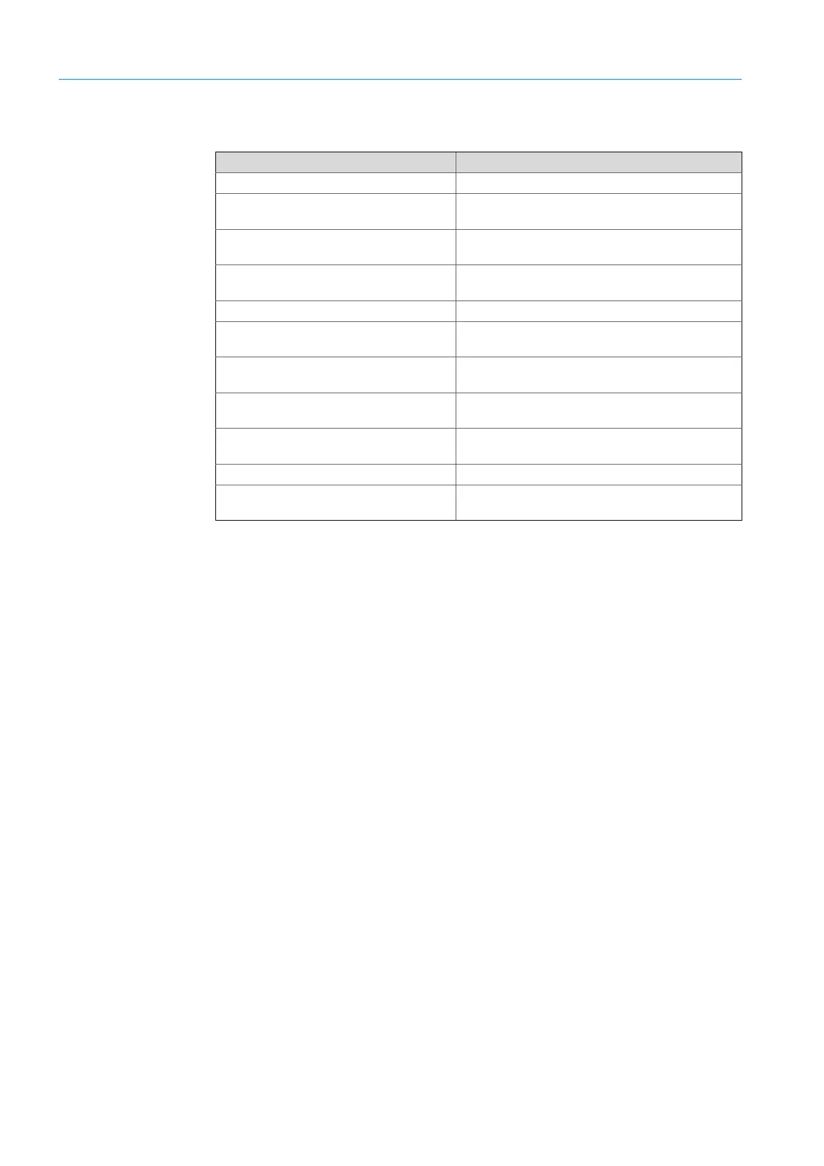
Procedure Reference
Removing the transport safety devices see “Transport safety devices”, page 29
Installing the device flange on the purge air
fixture
see “Installing the device flange on the purge air fix-
ture”, page 30
Aligning the measuring probe
see “Aligning the measuring probe in flow direction”,
page 31
For GPP probe: Electrical connection of
heater
see “For the GPP probe: Electrical connection”, page
32
Electrical connection of the SR-unit see “Electrical connection of the SR-unit”, page 33
Switching on the power supply
see “Switching on the power supply of the GM32”,
page 33
For GMP probe: Start-up of the purge air
supply
see “For GMP probe: Start-up of the purge air sup-
ply”, page 33
Installing the measuring probe in the gas
duct
see “Installing the measuring probe in the gas duct”,
page 34
Installing the SR-unit on the device flange
see “Installing the SR-unit on the device flange”, page
36
Optical fine alignment of the SR-unit see “Optical fine alignment of the SR-unit”, page 36
Installing weatherproof covers (option)
see “Installing weatherproof covers (option)”, page
39
Table 7: Installation steps overview

 Loading...


