24
8012707/ZVF9/V2-1/2019-04 | SICKOPERATING INSTRUCTIONS | GM32
Subject to change without notice
3 PREPARING THE GAS DUCT SIDE
3.5.4 Preparing the power supply
1 Requirements to connecting cable:
– Cross-section: 3 x 1.5 mm
2
– Temperature class: -40 ... +85 °C
2 Provide a separate external disconnecting device for:
– Connection unit (max. power input, see “System: GM32”, page 65).
– For GMP probe: Purge air unit (→ Technical data of the purge air unit)
– For GPP probe: Heater (max. power input, see “Gas-testable measuring probe (GPP)”,
page 67).
– Mark the disconnecting device as disconnecting device for the GM32.
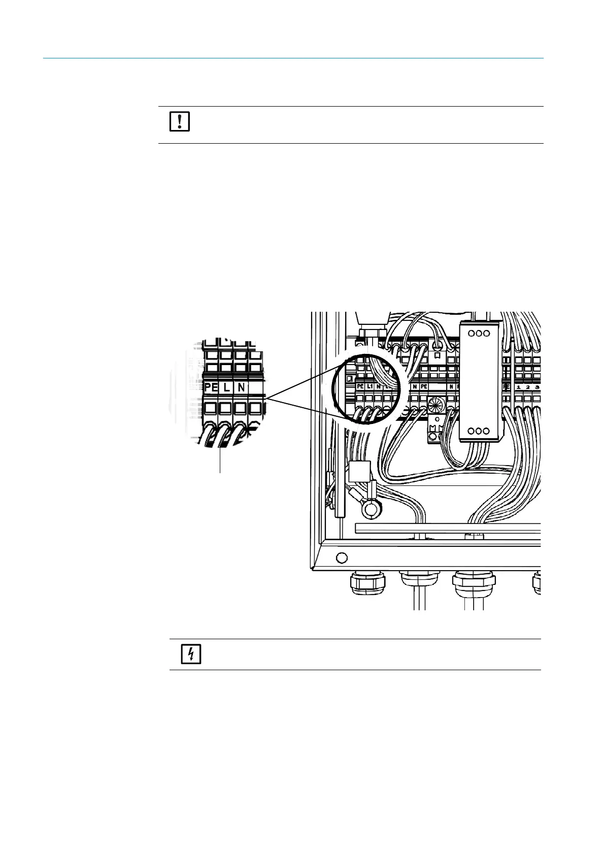
3 Lay the electric lines of the power supply to the connection unit and connect the power
supply in the connection unit.
Always connect a protective conductor to PE.
Fig. 9: Power connection in the connection unit
4
For GMP probe: Lay the electric lines to the purge air unit.
For GPP probe: Lay the electric lines for the probe heater.
Take precautions to prevent switching off the purge air supply accidentally.
▸ Attach a clearly visible warning against accidentally switching off the separation
equipment for the purge air unit.
Power supply
100 .. 240 V / 50 .. 60 Hz
Always connect a
protective conductor to PE.
The power supply must remain switched off until the GM32 is to be put into
operation.

 Loading...


