31
8012707/ZVF9/V2-1/2019-04 | SICK OPERATING INSTRUCTIONS | GM32
Subject to change without notice
START-UP 4
4.6 Aligning the measuring probe in flow direction
The fitting angle of the probe is already set before delivery when the gas flow direction has
been defined during project planning for the GM32.
A sticker marks the setting.
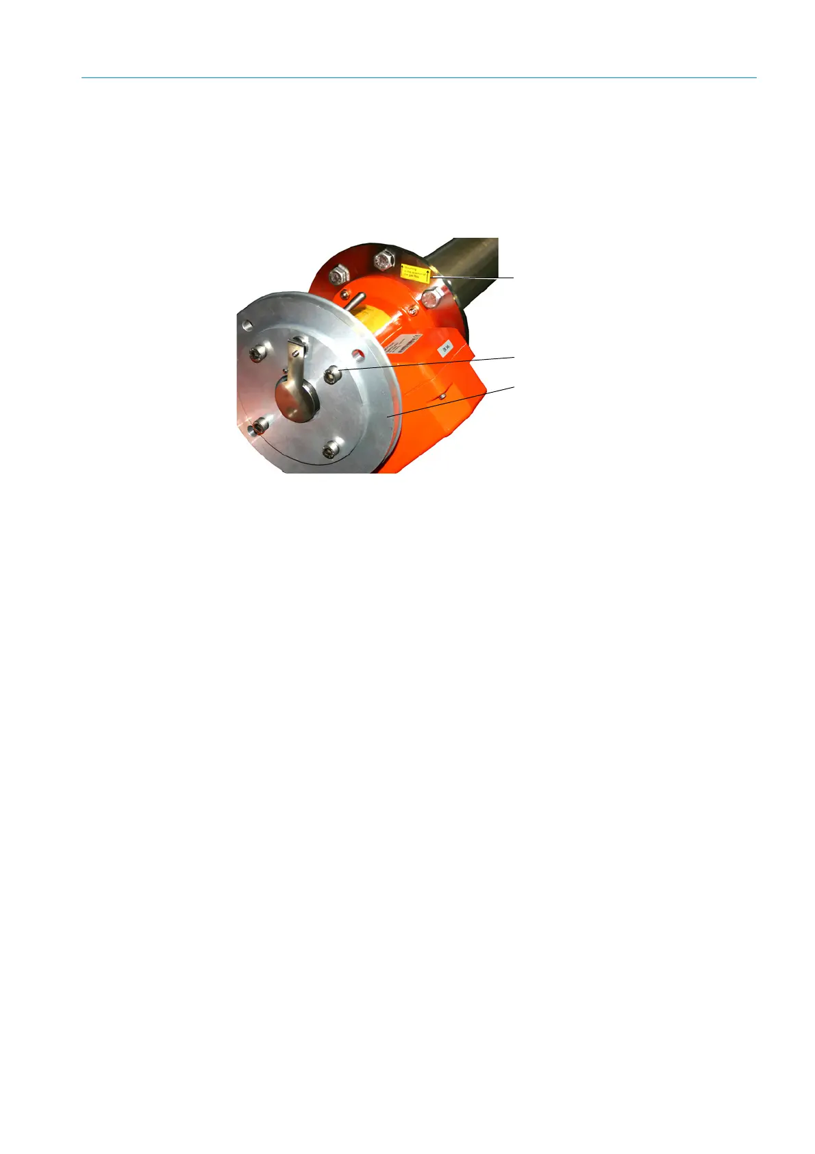
Fig. 13: Flow direction marking and setting
4.6.1 When the probe alignment has to be set
● The measuring gap must be aligned in sample gas flow direction.
● The SR-unit must be fitted vertically.
Rotate the device flange to align the probe.
To change the measuring probe alignment:
1 Loosen the 4 screws on the mounting ring, (see Fig. 13).
2 Rotate the device flange:
– The measuring gap must point in flow direction.
– The device flange must be positioned so that the SR-unit can be fitted in a vertical
position.
3 Tighten the screws on the mounting ring again to fasten the device flange in this
position.
Flow direction sticker
Mounting ring screws (4 pcs.)
Device flange

 Loading...


