68
8012707/ZVF9/V2-1/2019-04 | SICKOPERATING INSTRUCTIONS | GM32
Subject to change without notice
9 SPECIFICATIONS
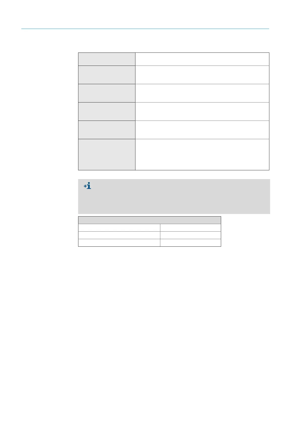
9.2.6 Connection unit
Description
Serves for on-site connection of the power supply and of data and sig-
nal cables.
Analog outputs
2 outputs:
0/4 ... 22 mA, 500 Ω
Per module, modules can be selected and extended as required.
Analog inputs
2 inputs
0/4 ... 22 mA, 100 Ω
Per module, modules can be selected and extended as required.
Digital outputs
4 outputs:
48 V AC/DC, 0.5 A, 25 W
Per module, modules can be selected and extended as required.
Digital inputs
4 inputs
3.9 V, 4.5 mA, 0.55 W
Per module, modules can be selected and extended as required.
Interfaces / Bus protocols
Ethernet
Ethernet
Ethernet
RS-485
Modbus TCP
OPC
SOPAS-ET
Modbus RTU (via optional interface module)
Table 25: Technical data connection unit
Further information and technical specifications for the GM32 system and its
components can be found in the following documentation:
● Technical Information GM32, measuring probe version
● Operating instructions, purge air unit SLV4
● Control unit SCU: See Operating Instructions SCU
● Operating Instructions Modular I/O System
Connections SCU I/O
Relay contact <-> PE 860 V AC
Relay contact <-> relay contact 860 V AC
Relay contact <-> actuation 1376 V AC
Table 26: Characteristic data for electric isolation

 Loading...


