23
8012707/ZVF9/V2-1/2019-04 | SICK OPERATING INSTRUCTIONS | GM32
Subject to change without notice
PREPARING THE GAS DUCT SIDE 3
The following Table shows the typical factory settings for the digital and analog inputs and
outputs.
3.5.3 Laying the electrical connection lines to the SR-unit
1 Lay the electrical connection lines from the connection unit to the SR-unit.
2 For GMP probe: Signal line from the purge air unit (connection on the purge air unit
→ Operating Instructions of the purge air unit) to the purge air fixture.
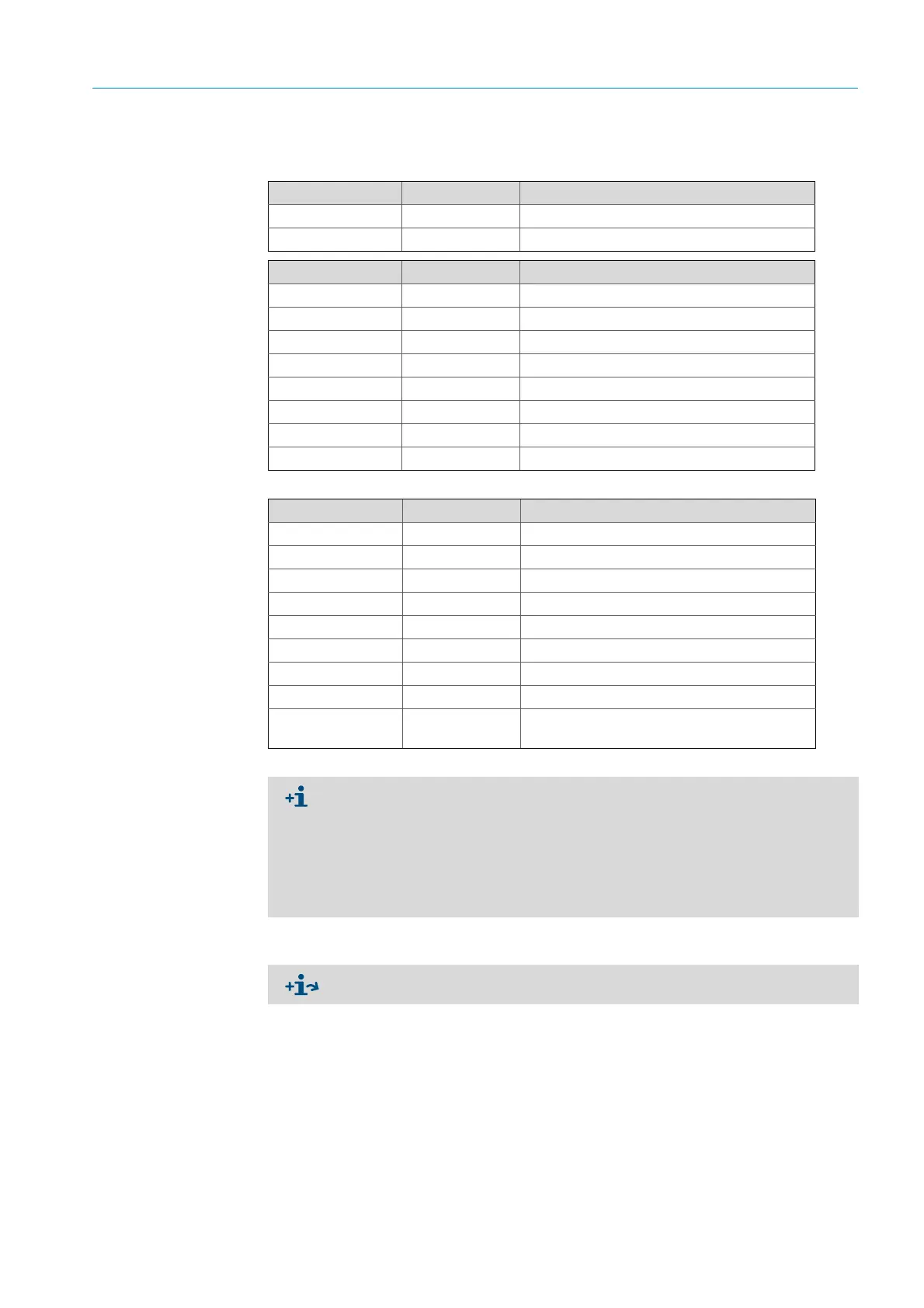
Analog output Pin assignment Function
AO 1 11, 12 User-specific
AO 2 21, 23 User-specific
Digital input Pin assignment Function
DI 1 11, 12 Check_cycle
DI 2 21, 22 Maintenance
DI 3 13, 14 Output_control_values
DI 4 23, 24 Disable_check_cycle
DI 5 11, 12
[1]
Purge_air_status
DI 6 21, 22
[1]
---
DI 7 13, 14
[1]
---
DI 8 23, 24
[1]
---
[1] On second module
Digital output Pin assignment Function
DO 1 11, 12 Failure (inverted)
DO 2 21, 22 Maintenance_Request
DO 3 13, 14 Not_measuring
DO 4 23, 24 Output_control_values
DO 5 11, 12
[1]
Uncertain
DO 6 21, 22
[1]
Extended
DO 7 13, 14
[1]
Purge_air_failure
DO 8 23, 24
[1]
No_function
Configurable Configurable
Measuring range switch-over
→ Technical Information GM32
[1] On second module
Information concerning the customer-specific module assignment
● The module layout from the left to the right always has this sequence: AO-AI-DO-DI
● The number of inputs and outputs is predetermined:
–2 x AO
–2 x AI
–4 x DO
–4 x DI
● Second measuring range: AO is alway on the right next to the respective component.
Electrical connections on GM32, see “Laying the electrical connection lines”, page 19

 Loading...


