19
8012707/ZVF9/V2-1/2019-04 | SICK OPERATING INSTRUCTIONS | GM32
Subject to change without notice
PREPARING THE GAS DUCT SIDE 3
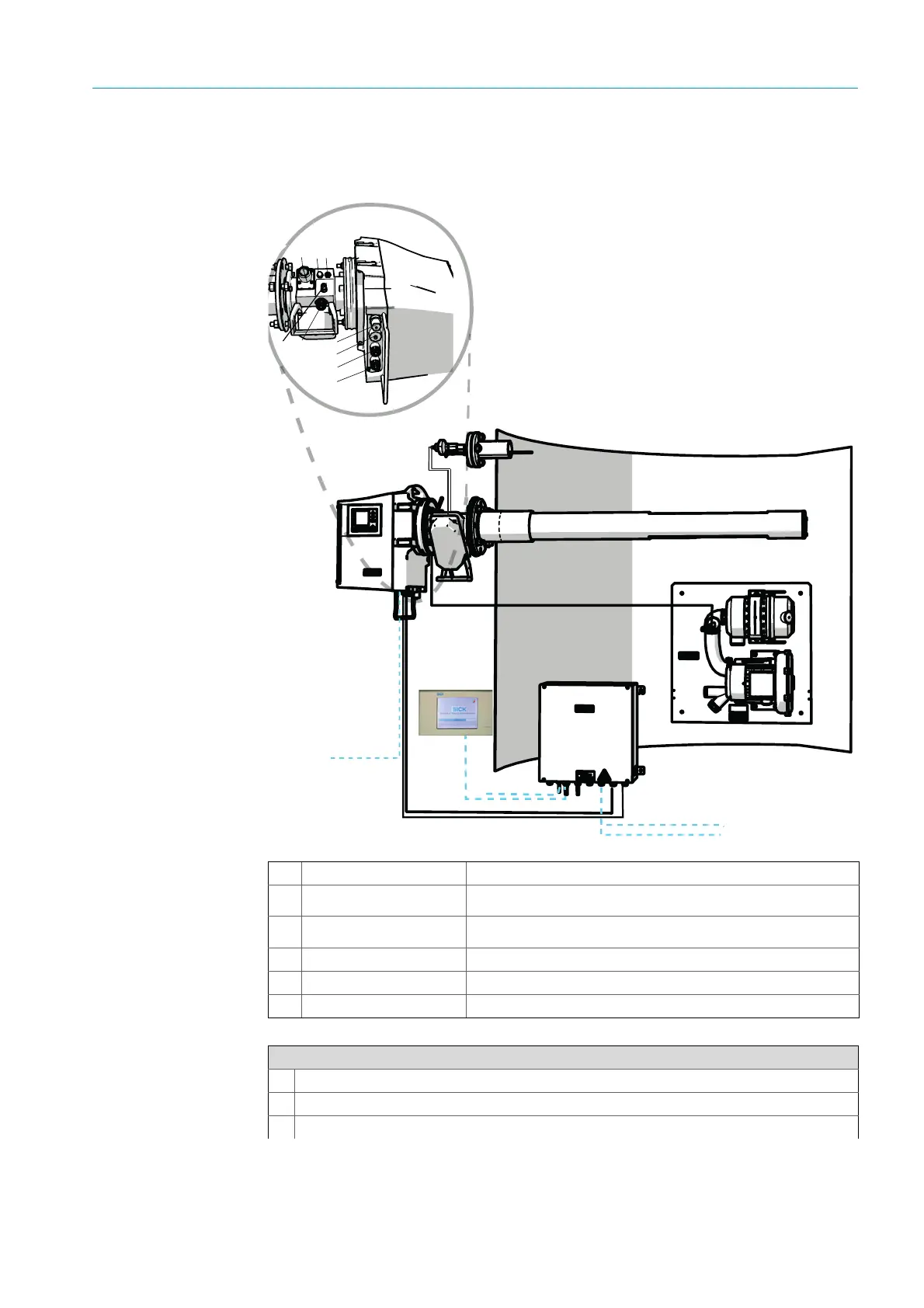
3.5 Laying the electrical connection lines
Fig. 6: Electrical connection diagram
%
$
§
b
132
6
54
7
!
"
8
9
ß
â
à
â
á
a
c
d
&
ã
Sender/receiver unit (SR)
Measuring probe (GMP or
GPP)
Measuring probe pre-assembled with purge air fixture
Pressure and temperature
sensor
Optional for probe
Purge air unit SLV4 Wiring and technical data, see Data Sheet SLV4
Connection unit (AU)
SCU (option)
Table 3: Hardware connection diagram
Connections of sender/receiver unit and purge air fixture (see detailed view)
Purge air supply connection
Temperature sensor connection
Purge air/filter monitor connection
Table 4: Signal cable

 Loading...


