30
8012707/ZVF9/V2-1/2019-04 | SICKOPERATING INSTRUCTIONS | GM32
Subject to change without notice
4 START-UP
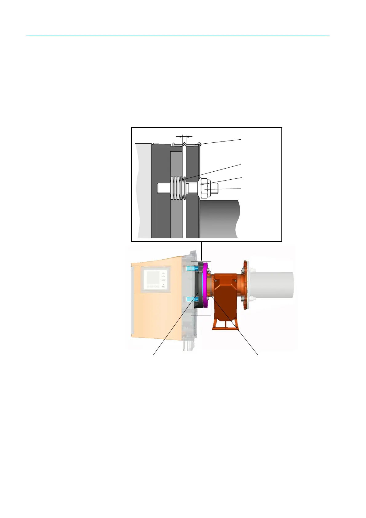
4.5 Installing the device flange on the purge air fixture
Remark on the GPP probe: The procedure for the GPP probe flange fixture corresponds to
the procedure shown here for the purge air fixture.
1 Recommendation: For easier handling during installation:
Remove the SR-unit from the device flange before installation, see “Swiveling out and
removing the SR-unit”, page 49.
2 Installation on the SR-unit side:
Fig. 12: Installing the device flange on the purge air fixture
a) Put 10 cup springs each, back-to-back, onto the three threaded bolts on the device
flange.
b) Pull the sealing ring over the flange of the purge air fixture and hang it loosely over the
purge air unit.
c) Push the device flange onto the purge air fixture.
d) Position the centering discs.
Notice: Observe the direction of the centering disc: The convex side must fit into the
groove on the purge air fixture.
e) Tighten the self-locking nuts with a jaw wrench (19 mm) so that the cup springs are
slightly compressed and an even gap of approx. 4 mm remains.
f) Fit the sealing ring above the gap, see Fig. 12.
Device flange
Purge air fixture
Gap: 4 ± 0.5 mm
Sealing ring
10 cup springs
Centering disc
Nut

 Loading...


