32
8012707/ZVF9/V2-1/2019-04 | SICKOPERATING INSTRUCTIONS | GM32
Subject to change without notice
4 START-UP
4.7 For the GPP probe: Electrical connection
1 Unscrew and take off the purge air fixture cover.
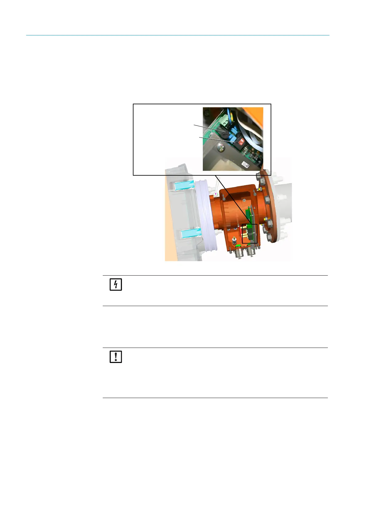
2 Check the switch setting for swapping the voltage to the available power voltage and
correct when necessary.
Fig. 14: Switch to select voltage and fuses
3
Check the fuses according to the available power voltage and replace when necessary.
4 Connect the power supply to the power voltage.
Line with three wires:
– Green-yellow: PE A protective conductor must be connected.
–Blue: N
–Brown: L1
Fuse holder
Switch to set voltage
NOTE: The fuses depend on the available power voltage.
▸ Only use the correct fuses.
– 230 V: 1.6 A (slow)
– 115 V: 2.5 A (slow)
NOTE: Danger of condensation
The GPP probe must have reached its operating temperature before being inserted
in the gas duct.
▸ First fit the GPP probe during final installation in the gas duct, see “Installing the
measuring probe in the gas duct”, page 34.
▸ Attach clearly visible warnings against accidental switching-off to all switching
devices where the GPP probe heater can be switched off.

 Loading...


