52
8012707/ZVF9/V2-1/2019-04 | SICKOPERATING INSTRUCTIONS | GM32
Subject to change without notice
6 MAINTENANCE
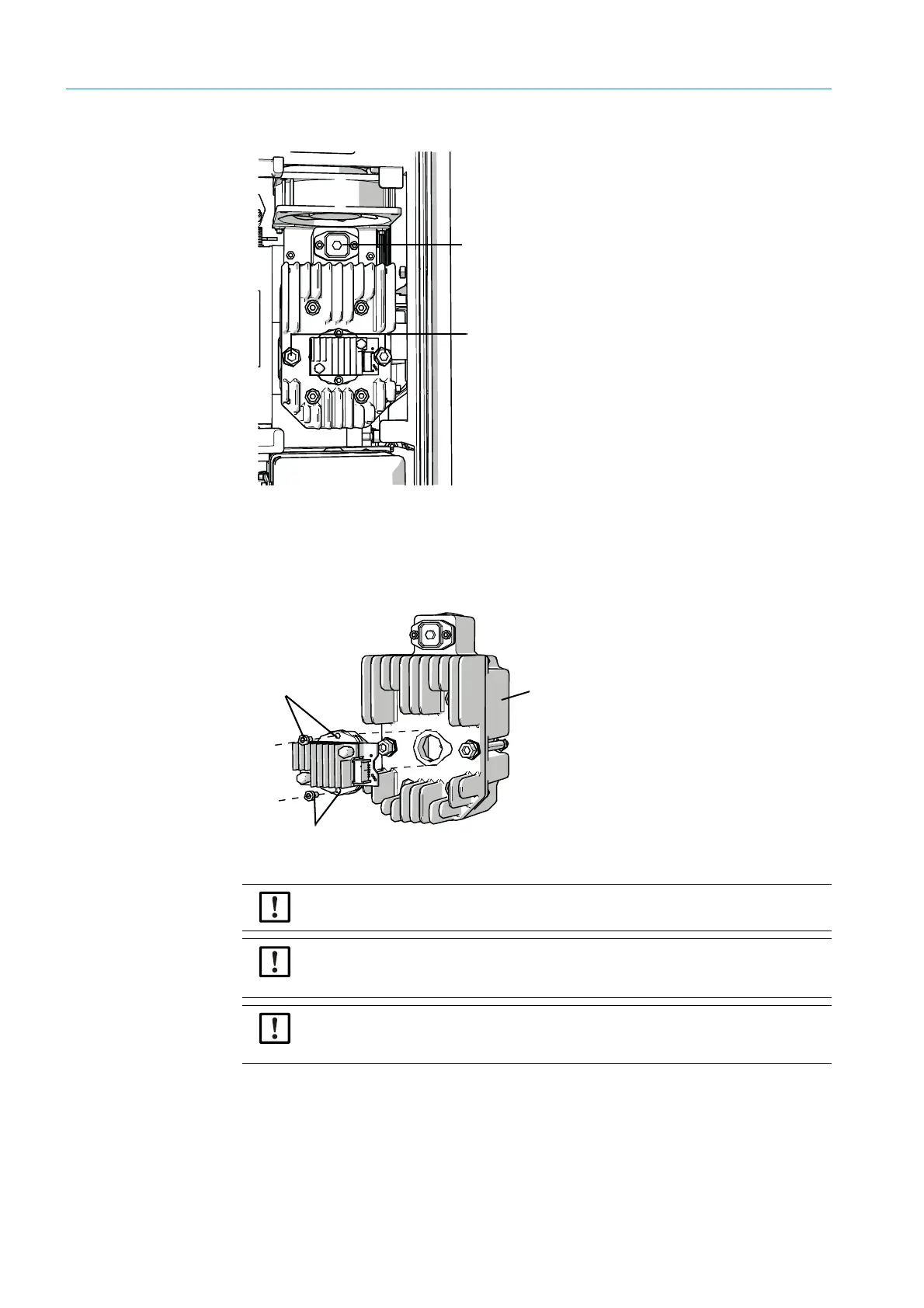
Fig. 36: Sender lamp
6 Optional: Loosen the 2 screws (5 mm Allen screw) on the sender lamp and take the
sender lamp off
.
Replacing the LED unit
Fig. 37: Remove the LED unit from the sender lamp
7
Loosen the two fastening screws of the LED unit and pull the LED unit off.
8 Plug in new LED unit and screw tight.
Connection of voltage supply line
Screws of sender lamp
Screws for fastening the LED unit
Sender lamp LowNOx
NOTE:
The fastening screws of the LED unit are not self-locking.
NOTE:
Risk of contamination of the optical mirrors in the device after removing the LED unit.
▸ Cover the opening to the optical mirror after removing the LED unit.
NOTE:
The optical surfaces can be contaminated when touched with your fingers.
▸ Avoid touching the optical surfaces with your fingers.

 Loading...


