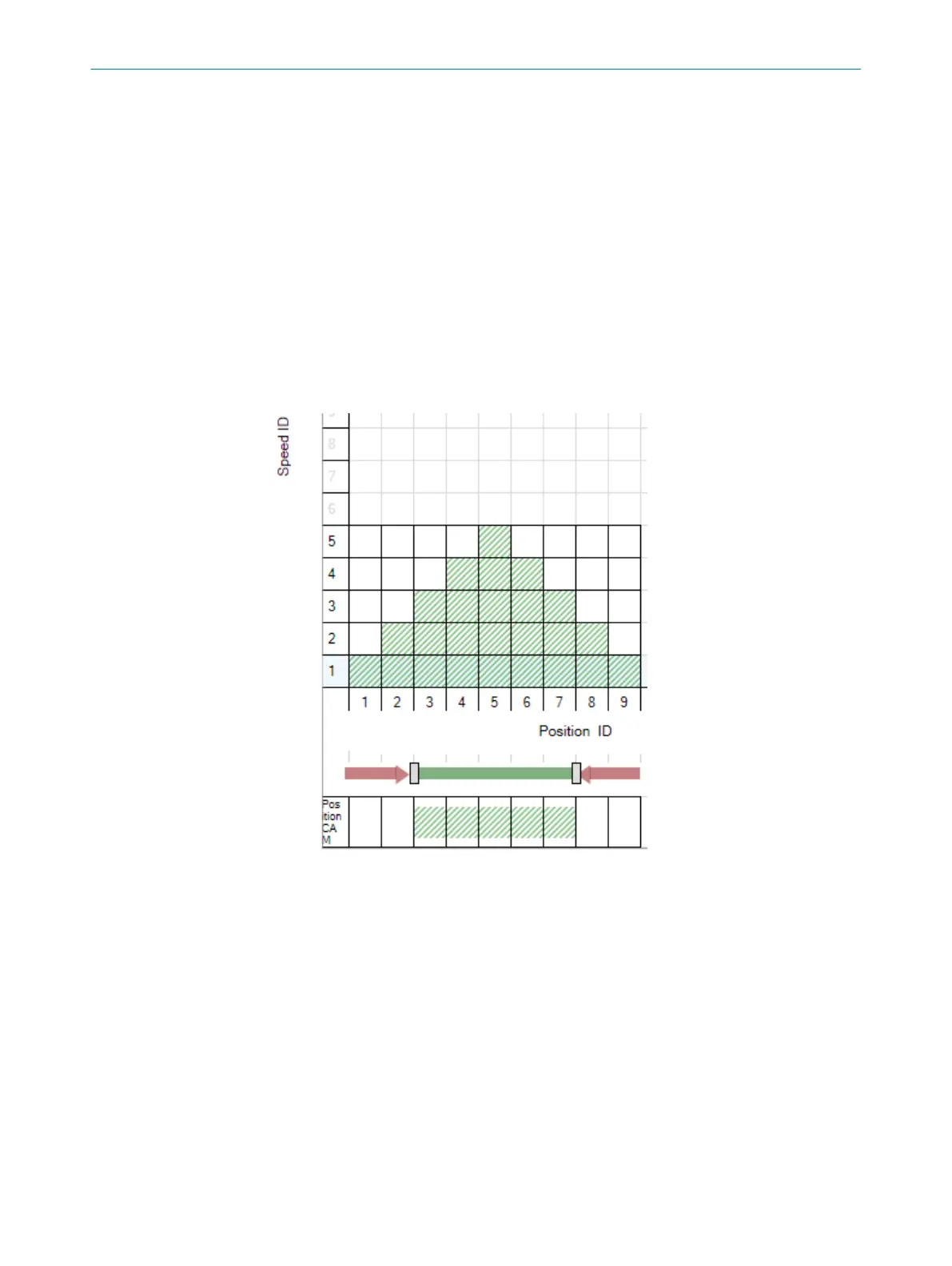
The position ID 2-5 position ranges are available within the application. However, the
per
mitted range is limited to position ID 3 and 4 because they have been configured as
safe cams. If the end position is overrun (i.e., the application is in position ID 2 or 5)
owing to a fault, the application can only move at a reduced speed (speed ID 2) in the
direction of position ID 3 or 4 (safe direction - SDI).
Several profiles can be used and selected depending on the direction. Further informa‐
tion about the functional scope of safe cam can be found in the Flexi Soft Designer
operating instructions.
Storage and retrieval system application example
Speed r
eduction is always safely monitored in two stages before the end positions. The
position ID 2 and 8 position ranges function as a buffer in case it is not possible to slow
down enough owing to a fault. As the speed cannot be very high in this instance owing
to the fact that monitoring begins at position ID 4 and 6, the buffer zone does not have
to be very large.
Figure 12: Safe cam setting range for a storage and retrieval system
CONFIGURATION 7
8020941/12O9/2019-08-05 | SICK O P E R A T I N G I N S T R U C T I O N S | Safe Linear Positioning
43
Subject to change without notice