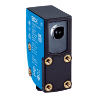
Table 106: Mounting
Check sequence Expected result Result OK?
1. Check the mounting of the safety
s
ystem.
•
T
he sensor system has been
mounted in accordance with these
operating instructions.
•
The sensor system must be
mounted within a permissible dis‐
tance of the bar code tape
(80 mm-120 mm).
•
There are no signs of manipulation
as far as the mounting is con‐
cerned.
Yes N
o
Electrical installation
T
able 107: Cable laying
Check sequence Expected result Result OK?
1. Check the cable laying.
•
T
he approved X-junction and, if
required, the permitted connection
cables from SICK are the only
options that can be used for electri‐
cally connecting the OLM sensors.
•
The X-junction is wired from the
FX3-MOC1 connector plug to the
SSI splitter within an electrical
installation area.
•
The maximum permitted lengths
have not been exceeded for cables.
•
The connector plugs for the OLM
sensors are mechanically secured
with tightened M12 threaded rings.
•
The connector plug for the FX3-
MOC1 is mechanically secured with
two screws (in the plug).
Yes N
o
Product description
T
able 108: Components
Check sequence Expected result Result OK?
1. Check that only approved OLM
sensor
s with the safety controller
have been used.
•
Onl
y the approved full OLM sensor
system has been used.
•
Individual sensors have not been
exchanged. The sensor system may
only be exchanged as one whole
unit (i.e., a mounting bracket with
sensors mounted on it).
•
The sensor system is only operated
with a Flexi Soft safety controller.
Yes N
o
Ambient conditions
T
able 109: Surrounding area
Check sequence Expected result Result OK?
1. Check the safety system for
manipula
tions in the surrounding
area.
•
T
here are no signs of manipulation
in the surrounding area, e.g., a bar
code having been affixed in front of
the sensors or dazzle from ambient
light.
Yes N
o
17 ANNEX
94
O P E R A T I N G I N S T R U C T I O N S | Safe Linear Positioning 8020941/12O9/2019-08-05 | SICK
Subject to change without notice
 Loading...


