Stage Description
Logic of a Stage
[loovpu03-090611-01.tif, 2, en_US]
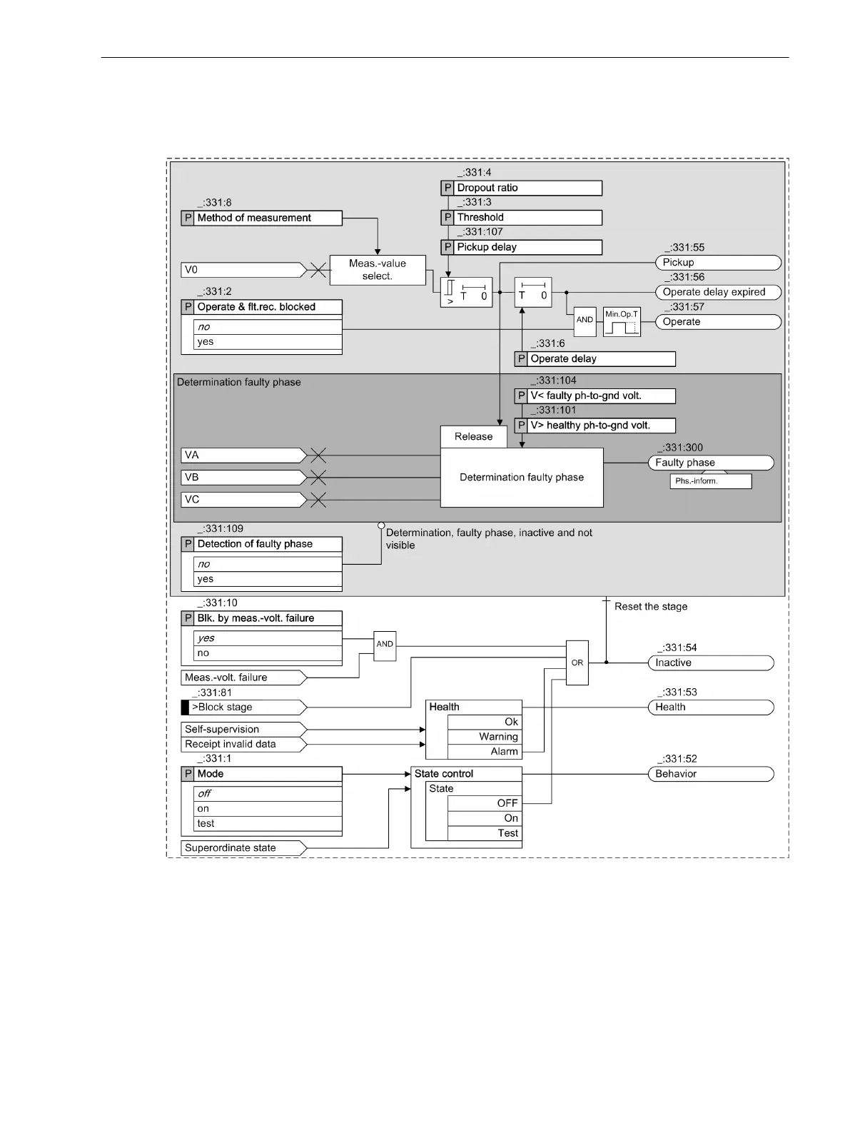
Figure 6-184
Logic Diagram of an Overvoltage Protection with Zero-Sequence Voltage/Residual Voltage
Stage
Measured Value, Method of Measurement
The device measures the residual voltage at the broken-delta winding. The measured voltage is converted to
the zero-sequence voltage V
0
. If the residual voltage is not available to the device as a measurand, the zero-
sequence voltage V
0
is calculated from the measured phase-to-ground voltages V
A
, V
B
, and V
C
using the
defining equation.
6.24.3
Protection and Automation Functions
6.24 Overvoltage Protection with Zero-Sequence Voltage/Residual Voltage
SIPROTEC 5, Overcurrent Protection, Manual 705
C53000-G5040-C017-8, Edition 07.2017