e1249d1
6
Fire & Security Products
Siemens Building Technologies Group
01.1999
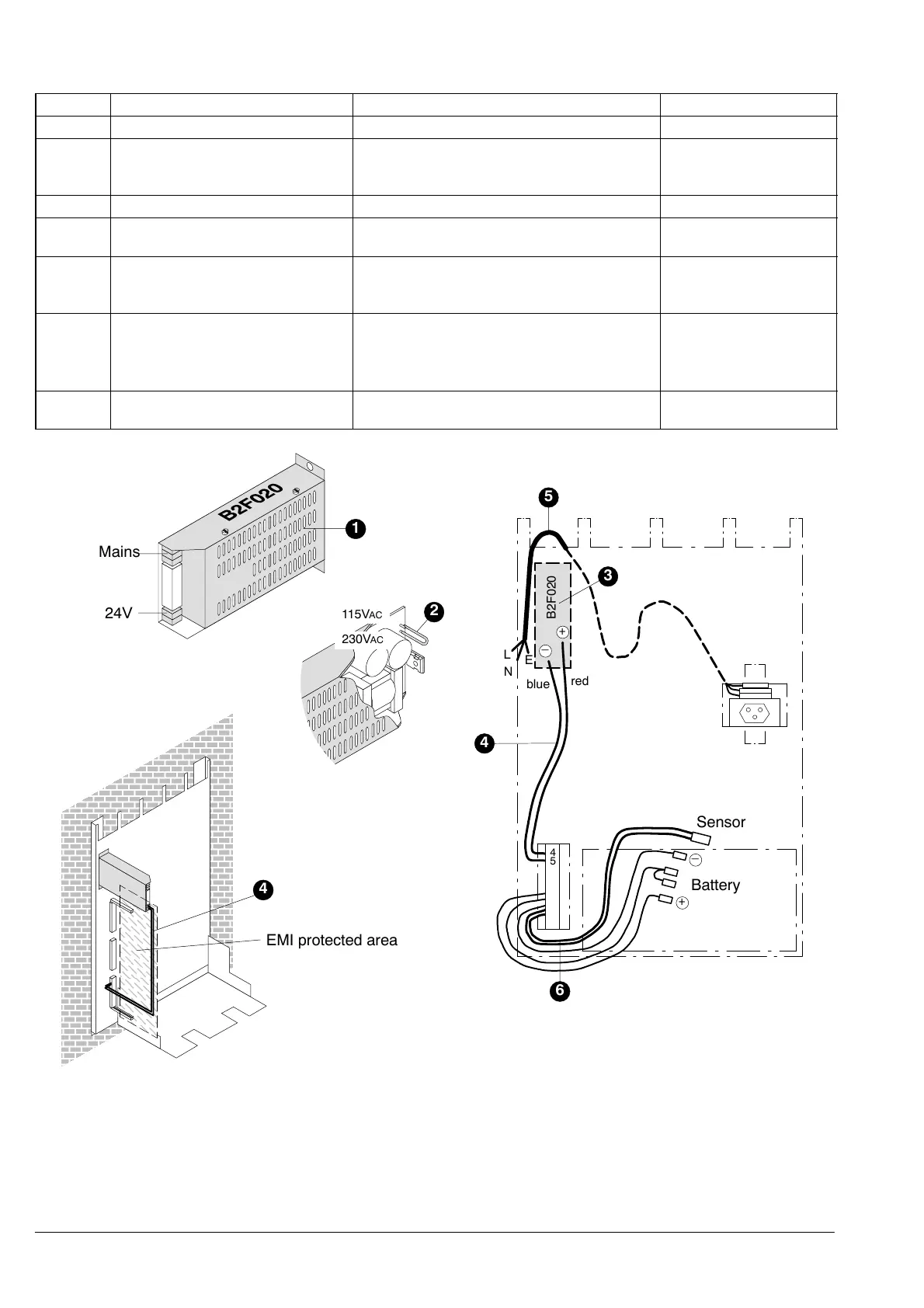
3.4.2 Power unit B2F020
Pos. Component Preparation Default
1 Metal cover Remove –
2 Jumper Check voltage setting,
change to setting for 115V
AC SUPPLY VOLTAGE
IF REQUIRED
230VAC SUPPLY VOLTAGE
1 Metal cover Replace –
3 Power unit Fit inside housing/to module chassis –
4 24V feed line Feed around front (through EMI protected
area) to power unit and connect to power
unit (24V output terminals)
–
5 Mains cable Connect to power unit (mains input termi-
nals)
See installation instructions
(documents e1273, e1274, e1275)
–
6 Battery connection Check properly connected –
ÑÑÑÑÑÑÑÑ
ÑÑÑÑÑÑÑÑ
ÑÑÑÑÑÑÑÑ
ÑÑÑÑÑÑÑÑ
ÑÑÑÑÑÑÑÑ
ÑÑÑÑÑÑÑÑ
ÑÑÑÑÑÑÑÑ
ÑÑÑÑÑÑÑÑ
ÑÑÑÑÑÑÑÑ
ÑÑÑÑÑÑÑÑ
ÑÑÑÑÑÑÑÑ
ÑÑÑÑÑÑÑÑ
ÑÑÑÑÑÑÑÑ
ÑÑÑÑÑÑÑÑ
ÑÑÑÑÑÑÑÑ
ÑÑÑÑÑÑÑÑ
115VAC
230VAC
24V
Mains
Sensor
–
+
Battery
B2F020
L
N
blue
red
4
5
6
+
–
E
4
5
EMI protected area
4
3
1
2

 Loading...


