e1249d1
7
Fire & Security Products
Siemens Building Technologies Group
01.1999
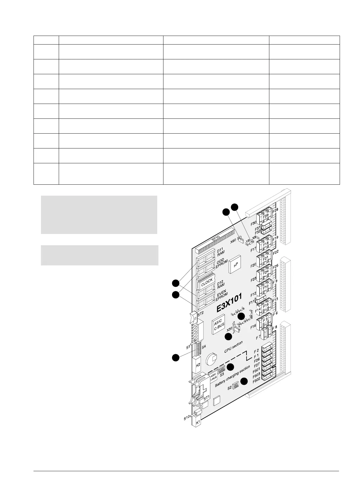
3.4.3 Master module E3X101 (supersedes E3X100)
Pos. Component Preparation Default
1 RAM modules (2x 512kx8)
RAM set Z3S070
install not installed
2 EPROMs (2x 512kx8)
EPROM set CCQ...
install
(note ODD and EVEN positions)
not installed
3 DIL switch S2 (battery type) Set to battery type used Type
«ALARMCOM (FIAM)»
4 DIL switch S3
I-Bus address of ”battery charging unit”
Set as per system documentation address 0
5 DIL switch S4
Service switch
For commissioning set S4-9 to ”ON”:
Test LEDs active
All switches set to OFF
6 Jumper Y8/X8
Contact assignment for ”remote alarm”
re-solder if ”break contact” is necessary on Y8
(= make contact)
7 Jumper X60
Ground short monitoring unit
Connect up contacts if ground short
monitoring unit is to be activated
Open
(monitoring unit inactive)
8 Jumper X30
C-Bus potential
Set according to hardware description
(document e1260)
Open
(floating)
9 Resistors
R178/179/196...199
Set as necessary (C-Bus impedance)
See hardware description
(document e1260)
Used for 110W imped-
ance (G51)
X15
X16
X17
1
2
5
3
4
For notes on ground short monitoring facili-
ty and C-Bus potential see page 103
7
6
9
8
CAUTION:
Take precautions against voltage surges
when inserting RAM modules and EPROMs.
Make sure modules are pushed fully home
in their slots.

 Loading...


