e1249d1
15
Fire & Security Products
Siemens Building Technologies Group
01.1999
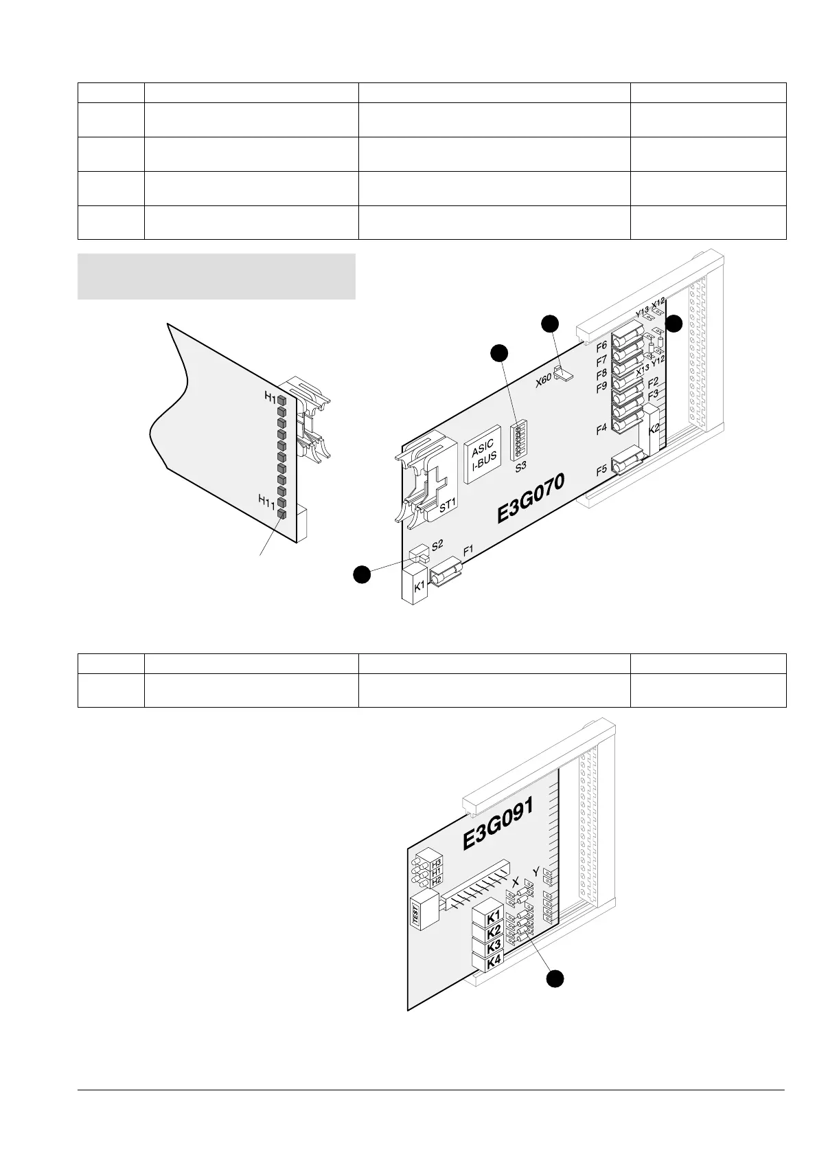
3.4.16 Control module «universal» E3G070
Pos. Component Preparation Default
1 DIL switch S3
I-Bus address
Set according to system documentation address 0
2 Maintenance switch S2
Activate test LEDs
Set to ON for commissioning Set to OFF
3 Jumpers X12/13 and Y12/13
Program transmission alarm/fault
Resolder if necessary (according to system
documentation)
On X13 and Y12
4 Jumper X60
Ground short monitoring unit
Connect up contacts if ground short moni-
toring unit is to be activated
Open (monitoring unit
inactive)
1
2
Test LEDs
3
For notes on ground short monitoring
see page 103
4
3.4.17 Remote transmission interface E3G091 (supersedes E3G090)
Pos. Component Preparation Default
1 Jumpers X1/Y1 to X6/Y6
Define make and break contacts
Resolder if necessary (according to system
documentation)
All jumpers in pos. X
1

 Loading...


