e1249d3
64
Fire & Security Products
Siemens Building Technologies Group
01.1999
4.8 Address allocation for digital inputs-/outputs on function units
Principle
Every digital input or output on an E3G... / E3L... function unit or on the CPU card is repre-
sented in the physical structure by a ’card input’ (’DE card in’) or ’card output’ (’DE card
out’) device. All of these devices are allocated to an element.
Inputs / outputs on cards need not be localized the location is given by the type of input
or output or the terminal.
The following elements may be linked to digital inputs:
’Digital element’ (’EL digital’)
’Digital detector element’ (’EL digital det.’)
’Digital manual call point element’ (’EL digital man.’)
’Command element’ (’EL command’)
’Output element with confirmation’ (’EL out 2’) as confirmation path only
’Remote transmission device element’ (’EL RT device’)
The following elements can be linked to digital outputs:
’Output elements without confirmation path’ (’EL out 1’)
’Output elements with confirmation path’ (’EL out 2’)
’Internal horn element’ (’EL int. horn’)
’External horn element’ (’EL ext. horn’)
’Alarm horn output element’ (’EL AL horn’)
’Supervised output element’ (’EL superv.’)
’Remote transmission channel element’ (’EL RT ch.’)
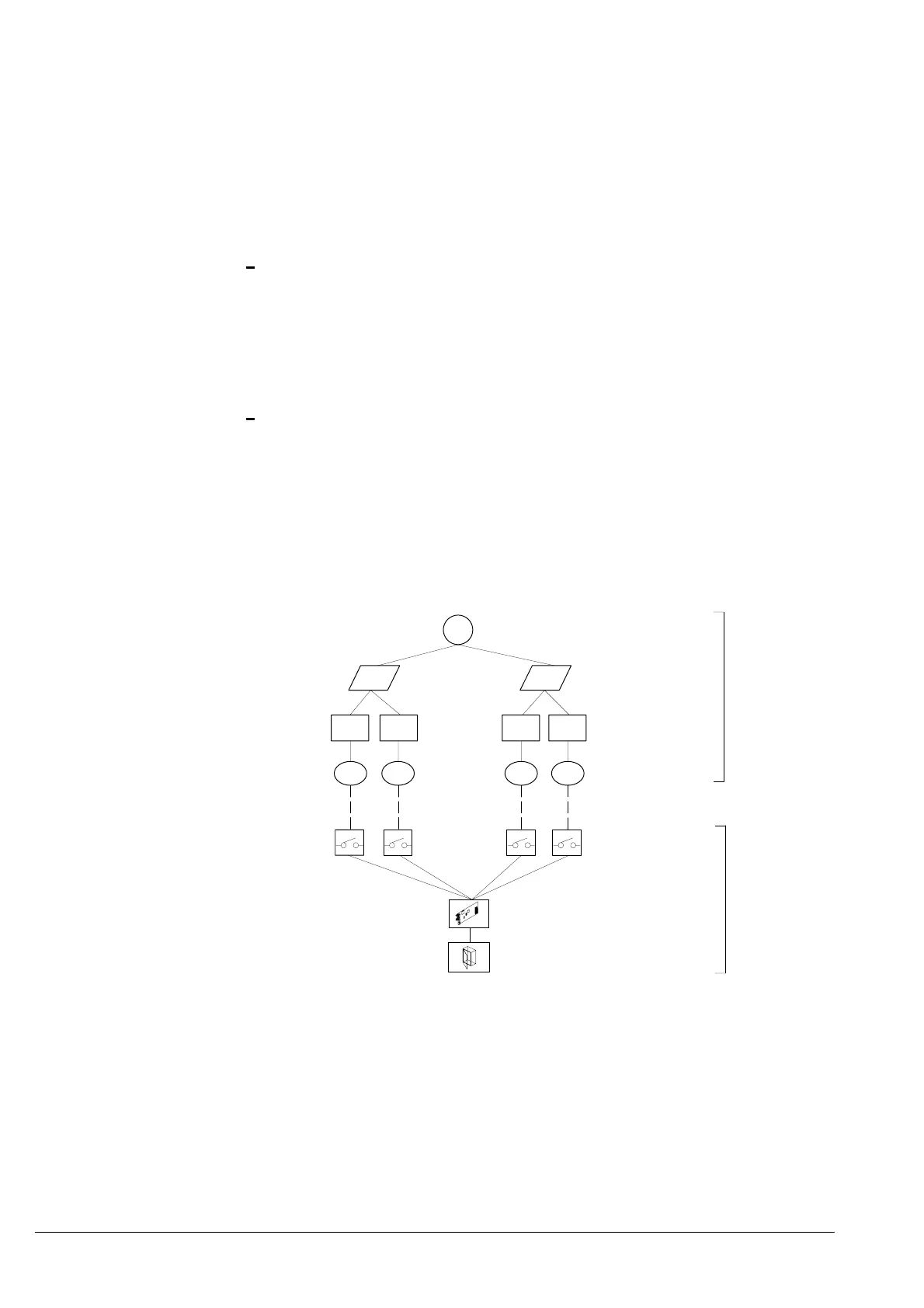
Links
Logical
structure
Physical
structure
’DE card out’
’FU I/O’
in in out out
’DE card in’
Zones
Devices
Elements
Sections
Station
Area
Example:
’ST CC11’
e.g. ’EL out 1’e.g. ’EL digital’
’AR ’
’SE control ’
e.g. ’ZO control 4’
’SE fire ’
e.g. ’ZO digital’
Function unit

 Loading...


