Failure and replacement of components during redundant operation
11.1 Failure and replacement of central components
CPU 410-5H Process Automation/CPU 410 SMART
170 System Manual, 10/2013, A5E32631667-AA
Note the different procedures.
Minor injury or damage to equipment is possible.
The procedure for replacing and input/output or function module differs for modules of the
S7-300 and S7-400.
Use the correct procedure when replacing a module. The correct procedure is described
below for the S7-300 and the S7-400.
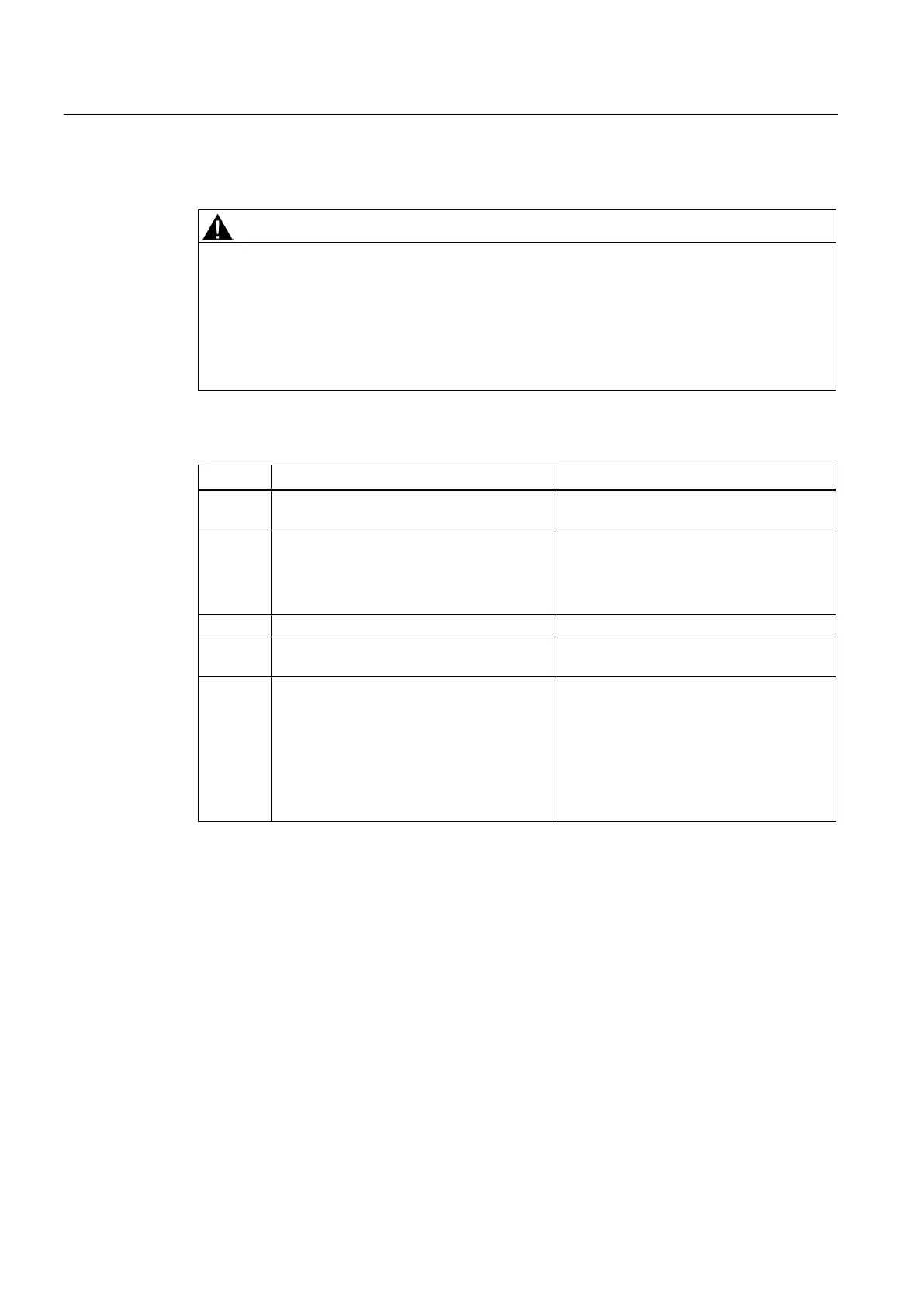
To replace signal and function modules of an S7-300, perform the following steps:
How does the system react?
1 Disconnect the module from its peripheral
power supply, if necessary.
2 Remove the failed module (in RUN mode).
• Both CPUs generate a remove/insert
interrupt and enter the event in the
diagnostic buffer and the system status
list.
Disconnect the front connector and wiring.
4 Plug the front connector into the new
-
5 Insert the new module.
• Both CPUs generate a remove/insert
interrupt and enter the event in the
diagnostic buffer and the system status
list.
• Parameters are assigned automatically
to the module by the CPU concerned
and the module is addressed again.
To replace signal and function modules of an S7-400, perform the following steps:
 Loading...


