Supplementary information
16.15 Cycle and response times of the CPU 410-5H
CPU 410-5H Process Automation/CPU 410 SMART
System Manual, 10/2013, A5E32631667-AA
281
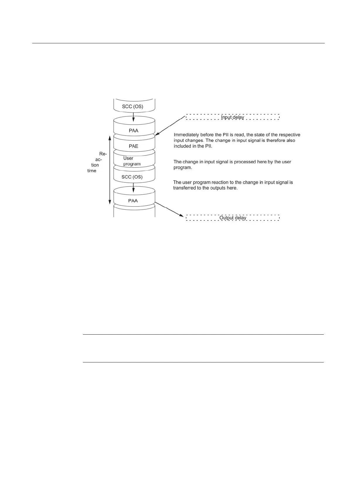
The figure below shows the conditions under which the shortest response time is achieved.
Figure 16-31 Shortest response time
The (shortest) response time is calculated as follows:
● 1 x process image transfer time of the inputs +
● 1 x process image transfer time of the outputs +
● 1 x program processing time +
● 1 x operating system processing time at the SCCP +
● Delay of the inputs and outputs
The result is equivalent to the sum of the cycle time plus the I/O delay times.
Note
If the CPU and signal module are not in the central controller, you must add twice the
runtime of the DP slave frame (including processing in the DP mas
ter).
 Loading...


