Supplementary information
16.15 Cycle and response times of the CPU 410-5H
CPU 410-5H Process Automation/CPU 410 SMART
System Manual, 10/2013, A5E32631667-AA
289
Calculating the interrupt response time
Minimum interrupt response time of the CPU
+ minimum interrupt response time of the
signal modules
+ cycle time on PROFIBUS DP or PROFINET IO
= Shortest interrupt response time
Minimum interrupt response time of the CPU
+ maximum interrupt response time of the
signal modules
+ 2 * cycle time on PROFIBUS DP or PROFINET IO
= Longest interrupt response time
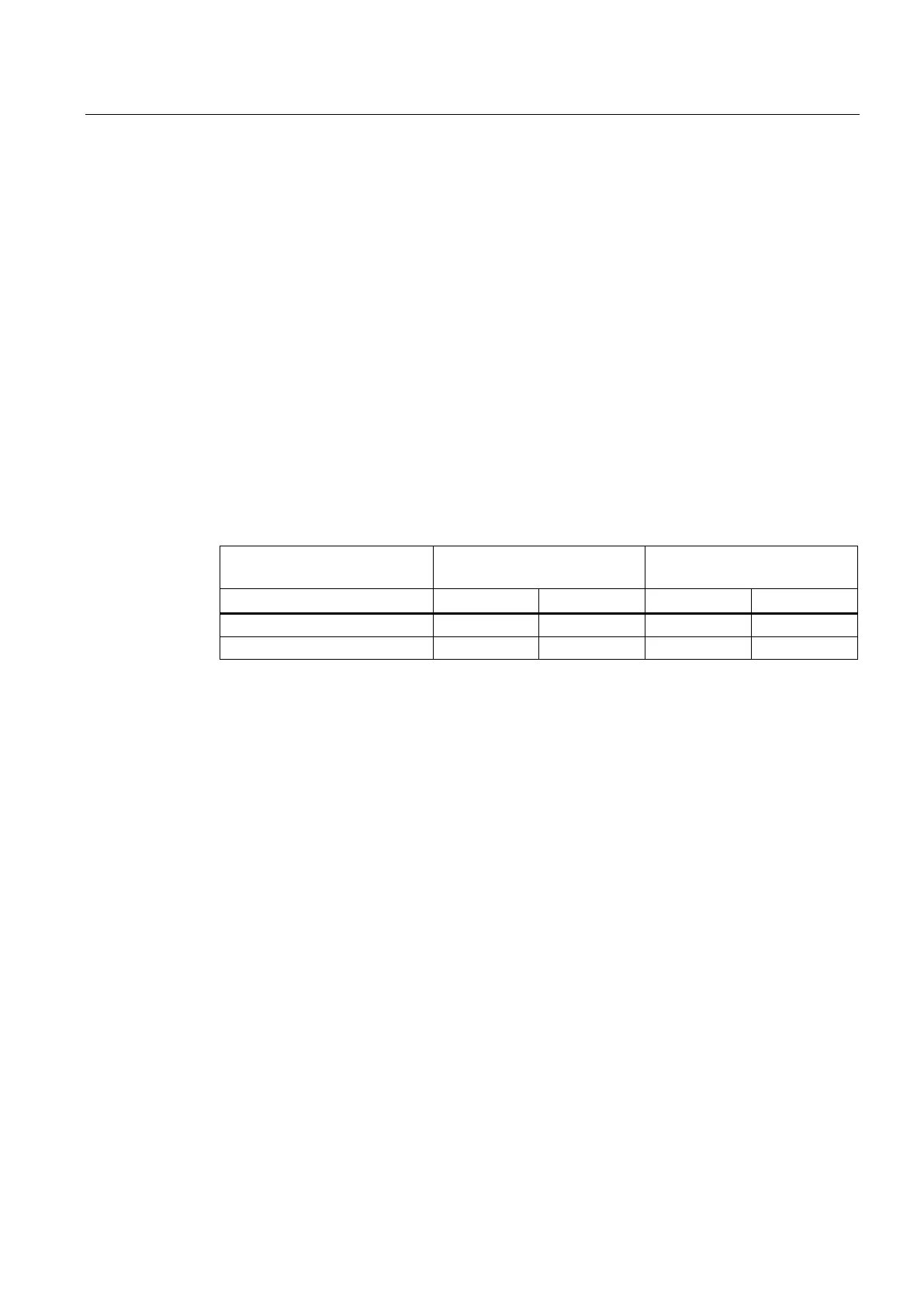
Hardware and diagnostic interrupt response times of the CPUs
Table 16- 19 Hardware and interrupt response times; maximum interrupt response time without
communication
Hardware interrupt response
times
Diagnostic interrupt response
times
CPU 410-5H stand-alone mode
Increasing the maximum interrupt response time with communication
The maximum interrupt response time is extended when the communication functions are
active. The additional time is calculated using the following formula:
CPU 410-5H t
v
= 100 µs + 1000 µs × n%, significant extension possible
where n = cycle load due to communication
The hardware interrupt response time of signal modules is made up as follows:
● Digital input modules
Hardware interrupt response time = internal interrupt processing time + input delay
You will find these times in the data sheet for the respective digital input module.
● Analog input modules
Hardware interrupt response time = internal interrupt processing time + conversion time
The internal interrupt processing time for analog input modules can be neglected. The
conversion times can be found in the data sheet for the individual analog input modules.
 Loading...


