I/O configuration variants
4.7 Connecting redundant I/O to the PROFIBUS DP interface
CPU 410-5H Process Automation/CPU 410 SMART
System Manual, 10/2013, A5E32631667-AA
75
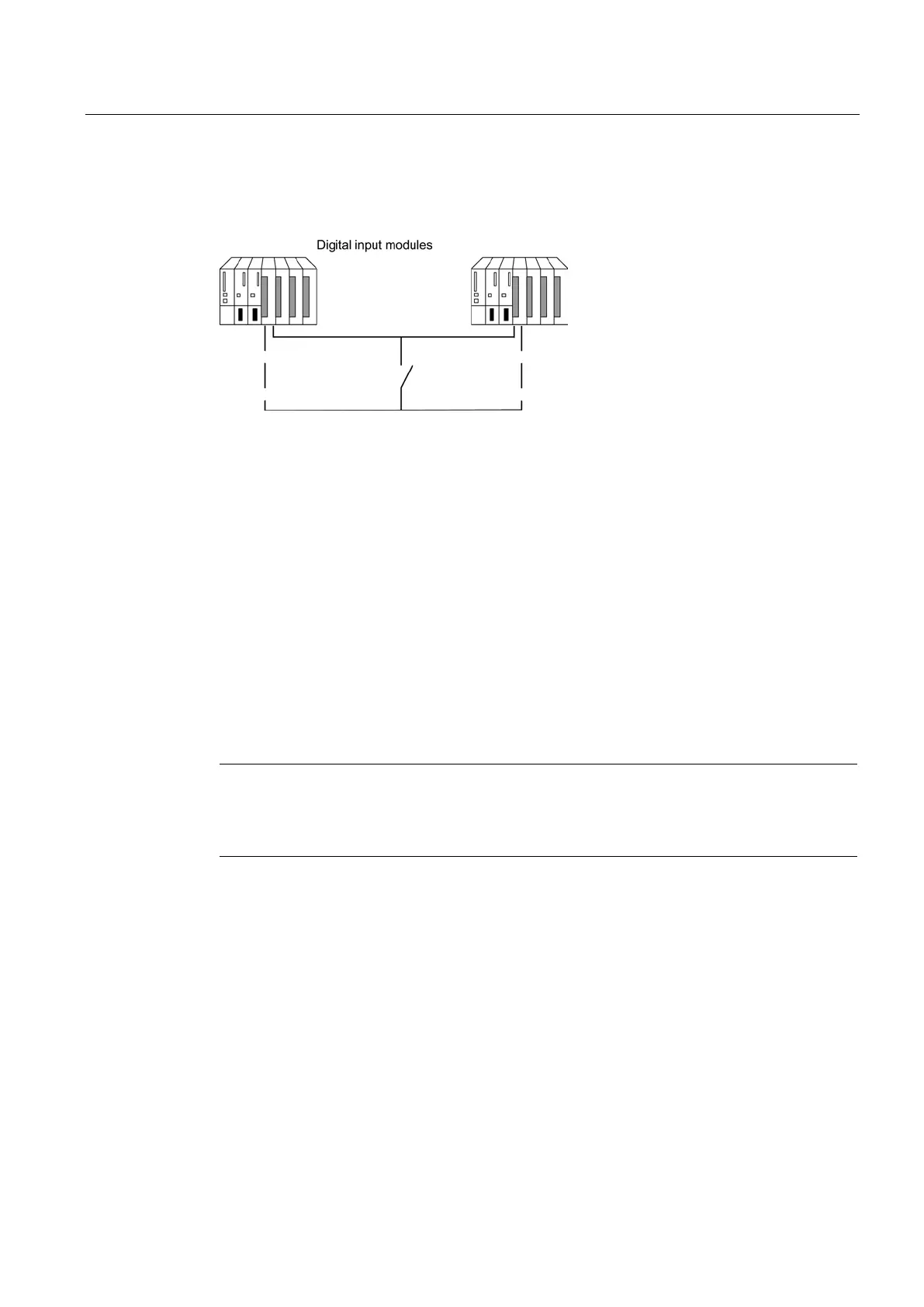
Using redundant digital input modules with non-redundant encoders
With non-redundant encoders, you use digital input modules in a 1-out-of-2 configuration:
Figure 4-16 Fault-tolerant digital input module in 1-out-of-2 configuration with one encoder
The use of redundant digital input modules increases their availability.
Discrepancy analysis detects "Continuous 1" and "Continuous 0" errors of the digital input
modules. A "Continuous 1" error means the value 1 is applied permanently at the input, a
"Continuous 0" error means that the input is not energized. This can be caused, for example,
by a short-circuit to L+ or M.
The current flow over the chassis ground connection between the modules and the encoder
should be the minimum possible.
When connecting an encoder to several digital input modules, the redundant modules must
operate at the same reference potential.
If you want to replace a module during operation and are not using redundant encoders, you
will need to use decoupling diodes.
If you do not use terminal modules, see the interconnection examples in the Appendix
Connection examples for redundant I/Os (Page 307).
Note
Remember that the proximity switches (Beros) must provide the current for the channels o
f
both digital input modules. The technical data of the respective modules, however, specify
only the required current per input.
 Loading...


