EasyManuals Logo

Siemens SIMATIC S7 System Manual

Siemens SIMATIC S7
866 pages
To Next Page IconTo Next Page
To Previous Page IconTo Previous Page
Page #712 background imageLoading...
Page #712 background image
Technical specifications
A.2 S7-200 SMART CPUs
S7-200 SMART
712 System Manual, V2.3, 07/2017, A5E03822230-AF
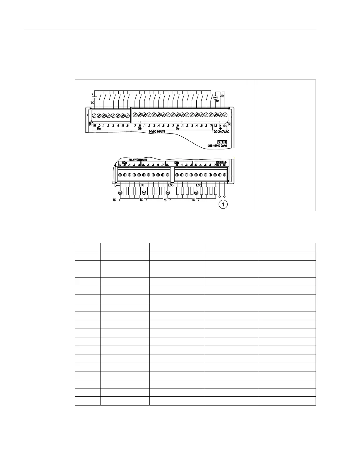
Table A- 49 Wiring diagram for the CPU SR40 AC/DC/Relay (6ES7288-1SR40-0AA0)
â‘ 
24 V DC Sensor Power
Out
Table A- 50 Connector pin locations for CPU SR40 AC/DC/Relay (6ES7288-1SR40-0AA0)
Pin
X10
X11
X12
X13
1
1M
DI a.7
1L
DQ b.0
2
DI a.0
DI b.0
DQ a.0
DQ b.1
3
DI a.1
DI b.1
DQ a.1
DQ b.2
4
DI a.2
DI b.2
DQ a.2
DQ b.3
5
DI a.3
DI b.3
DQ a.3
4L
6
DI a.4
DI b.4
2L
DQ b.4
7
DI a.5
DI b.5
DQ a.4
DQ b.5
8
DI a.6
DI b.6
DQ a.5
DQ b.6
9
--
DI b.7
DQ a.6
DQ b.7
10
--
DI c.0
DQ a.7
L+ / 24 V DC Out
11
--
DI c.1
3L
M / 24 V DC Out
12
--
DI c.2
--
--
13
--
DI c.3
--
--
14
--
DI c.4
--
--
15
--
DI c.5
--
--
16
--
DI c.6
--
--
17
--
DI c.7
--
--
18 -- L1 / 120 - 240 V AC -- --

Table of Contents

Other manuals for Siemens SIMATIC S7

Questions and Answers:

Question and Answer IconNeed help?

Do you have a question about the Siemens SIMATIC S7 and is the answer not in the manual?

Siemens SIMATIC S7 Specifications

General IconGeneral
BrandSiemens
ModelSIMATIC S7
CategoryController
LanguageEnglish

Related product manuals