Configuration
3.20 Configuring data points
Configuration - DNP3
Configuration Manual, 11/2018, C79000-G8976-C508-01
111
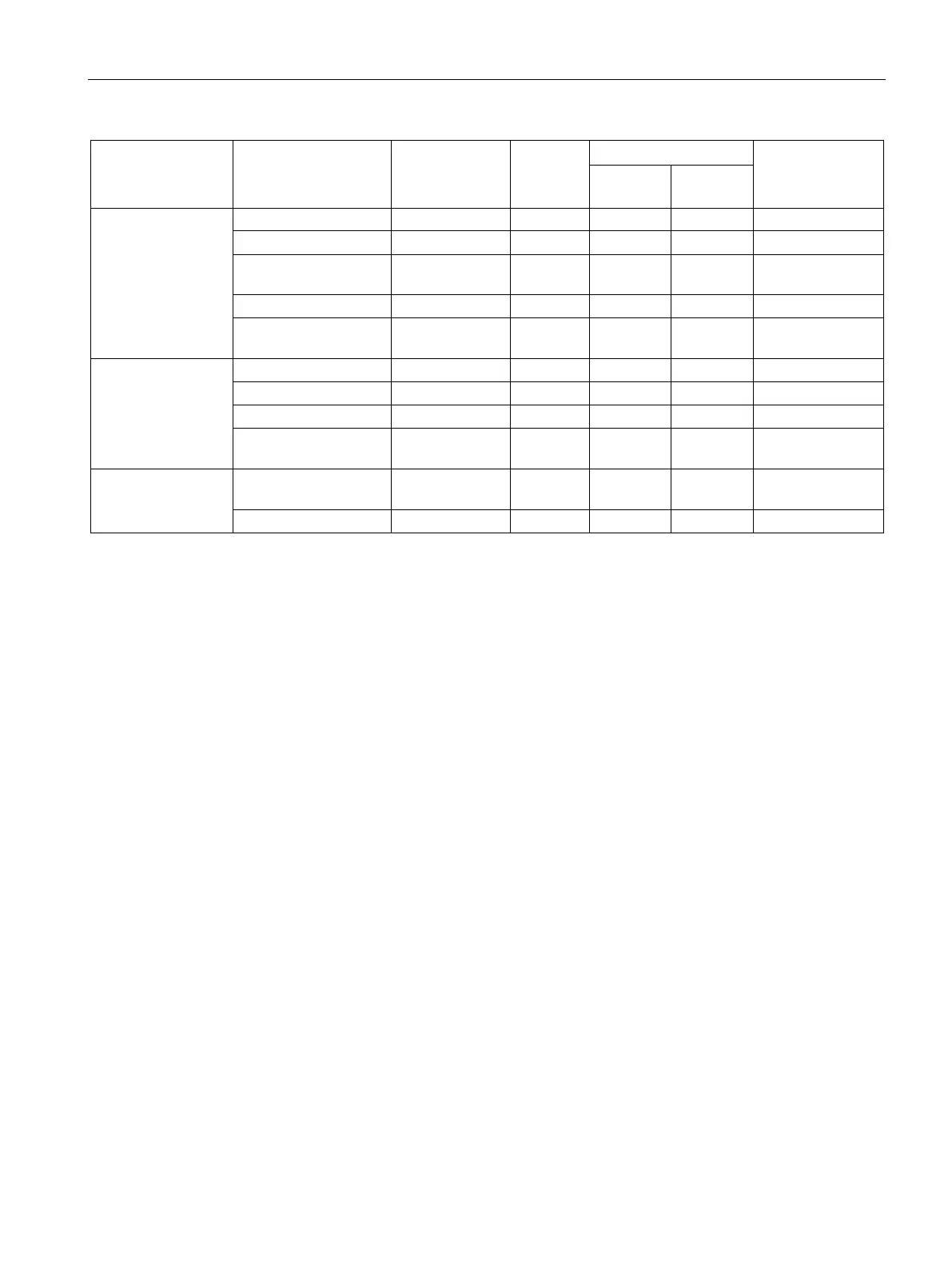
Format (memory
requirements)
DNP3 object
group
[variation]
Floating-point num-
ber (32 bits)
Analog Input Event
[5, 7] in Real - Q, M, DB
Analog Output Sta-
4)
[3] out Real - Q, M, DB
Analog Output
[3] out Real - Q, M, DB
Analog Output
4)
[5, 7] out Real - Q, M, DB
Floating-point num-
ber (64 bits)
Analog Output
4)
[6, 8] out LReal - Q, M, DB
Data block
(1...64 bytes)
5)
Octet String / Octet
[ - ] in, out
5)
5)
DB
5)
5)
5)
This object group can be configured in the data point editor of STEP 7 using the substitute object group 12.
This object group can be configured in the Data point editor of STEP 7 using the substitute object group 20.
This object group can be configured in the Data point editor of STEP 7 using the substitute object group 22.
This object group can be configured in the Data point editor of STEP 7 using the substitute object group 41.
With these data point types, contiguous memory areas up to a size of 64 bytes can be transferred. All S7 data types with
a size between 1 and 64 bytes are compatible.
Explanation of the table footnotes
1)
2)
3)
4)
: Configuring data points using substitute object
groups
The initial data point types of the following object groups can be configured using the
substitute object groups listed above:
● 10 [2]
● 11 [1, 2]
● 21 [1, 2, 5, 6]
● 23 [1, 2, 5, 6]
● 40 [1, 2, 3]
● 42 [1, 2, 4, 5, 6, 7, 8]
Use the specified substitute object group for the configuration.
Assign each data point on the master using the configurable data point index in STEP 7. The
data point of the station module is then assigned to the corresponding data point on the
master.
Example of configuring the data point Binary Output (10 [2])
The data point is configured as follows:
In the station module as Binary Command (12 [1])
On the master as Binary Output (10 [2])