The SINAUT Configuration Tool
6.4 The connection configuration
TIM DNP3
144 System Manual, 12/2015, C79000-G8976-C253-04
The entries in the connection tables must be interpreted as follows:
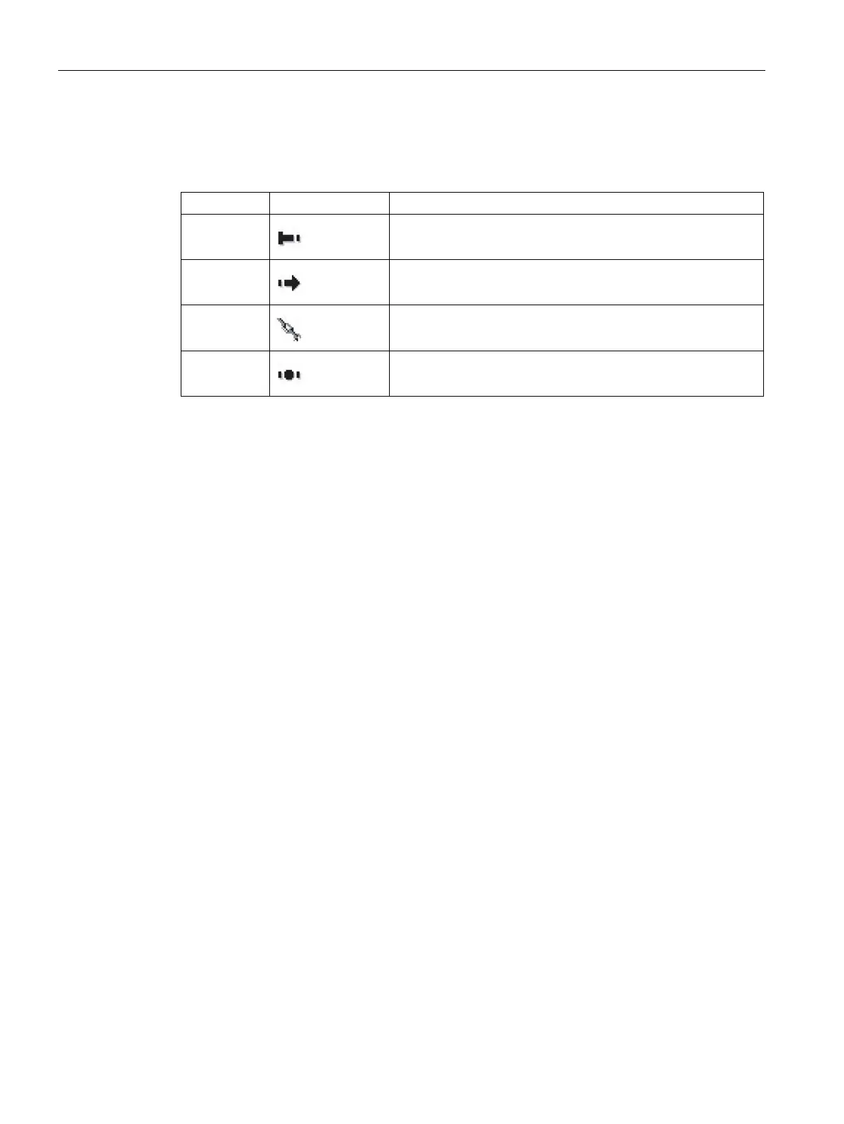
Table 6- 1 Symbols in the connection list of the connection configuration
1
Connection starting point
2
Connection end point
3
Alternative path
4
Connection node over which the connection runs
Invalid connections are displayed in red as shown in the example of a connection that no
longer exists due to reconfiguration (see figure).
The labeling of the individual connection point in the basic setting describes the relevant
subscriber with:
Subscriber number / Station name / Module / Interface.
Example: 5 / Station 3 / CPU 312 / MPI (2)
The representation can be set to meet individual requirements using the Extras / Options
menu.
Rules for connection configuration (DNP3)
● For each path (physical network) only one connection can be configured.
● Between a DNP3 master station and a DNP3 station, a maximum of 2 paths can be
configured.
Exception: a redundant DNP3 master station is involved. In this case, a station TIM can
have a maximum of 4 connections on 2 paths (interfaces).
● In DNP3 dedicated line networks, connections can only be configured between the
following partners:
– DNP3 master station - DNP3 station
DNP3 master station - node station
Node station - DNP3 station
● In Ethernet and dial-up networks, connections between two stations can also be selected
for direct communication.

 Loading...


