6
05.01
6.7 DC link options
6-183
© Siemens AG 2008 All Rights Reserved
SIMODRIVE 611 Configuration Manual (PJU) – 05/2008 Edition
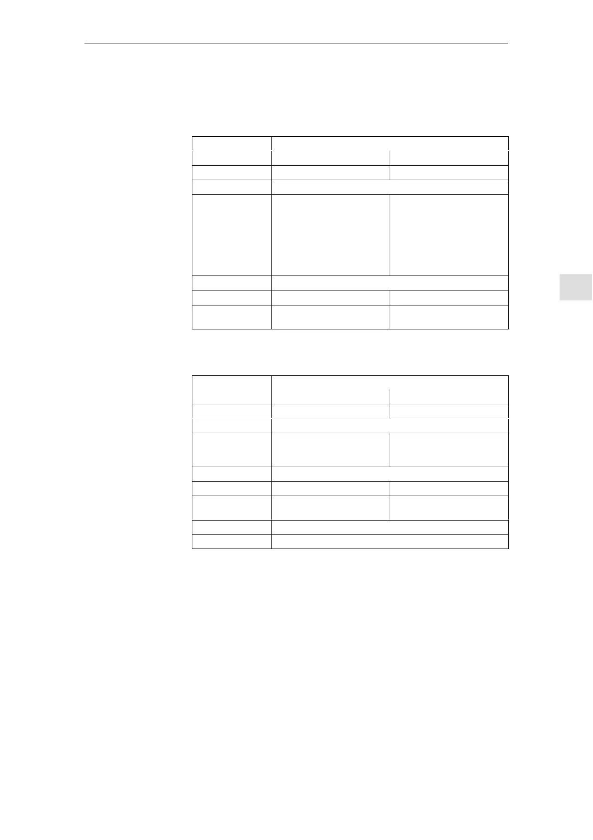
The following technical data applies:
Table 6-13 Technical data of the central capacitor modules
Designation Central modules
4.1 mF 20 mF
Order number 6SN11 12–1AB00–0BA0 6SN11 12–1AB00–0BA0
Voltage range V
DC
350 ... 750 V
Storage capacity
w = 1/2 x C x V
2
V
DC
steady–state
(examples)
600 V ––> 738 Ws
680 V ––> 948 Ws
V
DC
steady–state
(examples)
600 V ––> 3 215 Ws
680 V ––> 4 129 Ws
Note:
As a result of the internal pre–
charging resistor, the voltage at
the capacitors is only approx.
0.94 x V
DC
.
Temperature range 0 _C to +55 _C
Weight approx. 7.5 kg approx. 21.5 kg
Dimensions W x H x D
100 x 480 x 211 [mm]
W x H x D
300 x 480 x 211 [mm]
Table 6-14 Technical data of the distributed capacitor modules
Designation Distributed modules
2.8 mF 4.1 mF
Order number 6SN11 12–1AB00–1AA0 6SN11 12–1AB00–1BA0
Voltage range V
DC
350 ... 750 V
Storage capacity
w = 1/2 x C x V
2
V
DC
steady–state
(examples)
600 V ––> 504 Ws
680 V ––> 647 Ws
V
DC
steady–state
(examples)
600 V ––> 738 Ws
680 V ––> 948 Ws
Temperature range 0 _C to +55 _C
Weight 5.3 kg 5.8 kg
Dimensions W x H x D
100 x 334 x 231 [mm]
W x H x D
100 x 334 x 231 [mm]
Connection AWG 12 ... AWG 6 (4 ... 16 mm
2
) finely stranded
Degree of protection IP 20
The storage capacity in dynamic operation and for regenerative braking is
calculated as follows:
Formula: w = ½ S C S (V
2
DC
link
max
– V
2
DC
link
n
)
Assumptions for the example:
Capacitance of the capacitor battery C = 4.1 mF
Rated DC link voltage V
DClinkn
= 600 V
Maximum DC link voltage V
DClinkmax
= 695 V
––> w = ½ S 4.1 S 10
–3
F S ((695 V)
2
– (600 V)
2
) = 252 Ws
In addition, 252 Ws for each C = 4.1 mF module can be stored for this voltage
range.
Technical data
Examples for the
calculation
6 Infeed Modules11.0502.07