9
05.01
9.1 Installation and connecting–up regulations
9-337
© Siemens AG 2008 All Rights Reserved
SIMODRIVE 611 Configuration Manual (PJU) – 05/2008 Edition
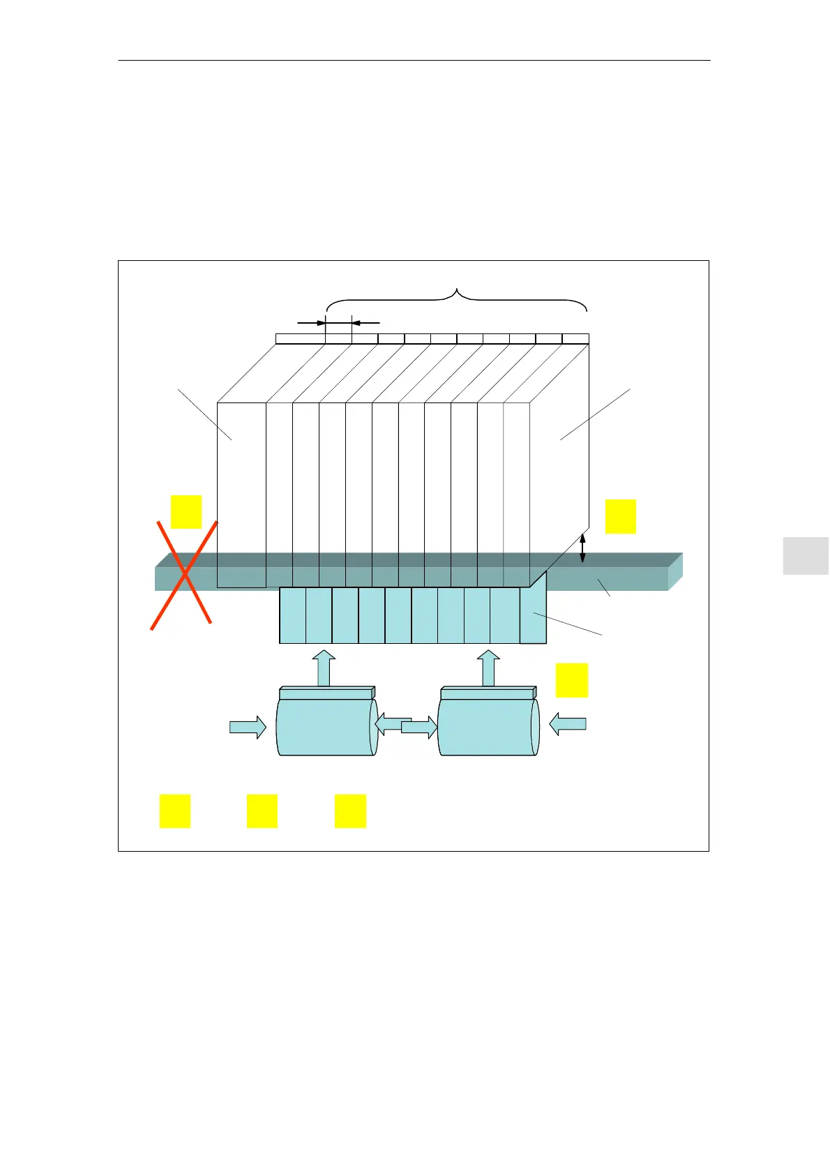
Measures are shown in the following diagram if the following conditions/ar-
rangements simultaneously exist in the cabinet:
S Number of power modules (50 mm wide) N >10
S Shield plate
S Channel cable
Supplementary fan
>200 mm
A
B
C
N >10
50 mm
Supplementary fan
The following measures must be applied as a minimum in order to ensure adequate air intake:
A
or
B
or
C
Power modulesInfeed module
Shield plate
Channel cable
Fig. 9-6 Measures when building the cabinet
Cables may not be routed over modules; the ventilation grilles may not be cov-
ered. The 50 mm wide devices are especially critical.
Air intake when
arranging power
modules
Cable routing
9 Cabinet Desi
n and EMC11.05