5
5.6 Net data (PKW and PZD area)
5-273
Siemens AG 2005 All Rights Reserved
SIMODRIVE 611 universal Description of Functions (FBU) – 04.05 Edition
5.6.7 Parameter area (PKW area)
For PPO types 1, 2 and 5 for the net data (useful data), a parameter
range with 4 words is also transferred.
The following tasks are possible using the parameter range:
Request parameter value (reading parameters)
Change parameter value (write into parameters)
Request number of array elements
The PKW area comprises the parameter ID (PKE), the sub–index (IND)
and the parameter value (PWE).
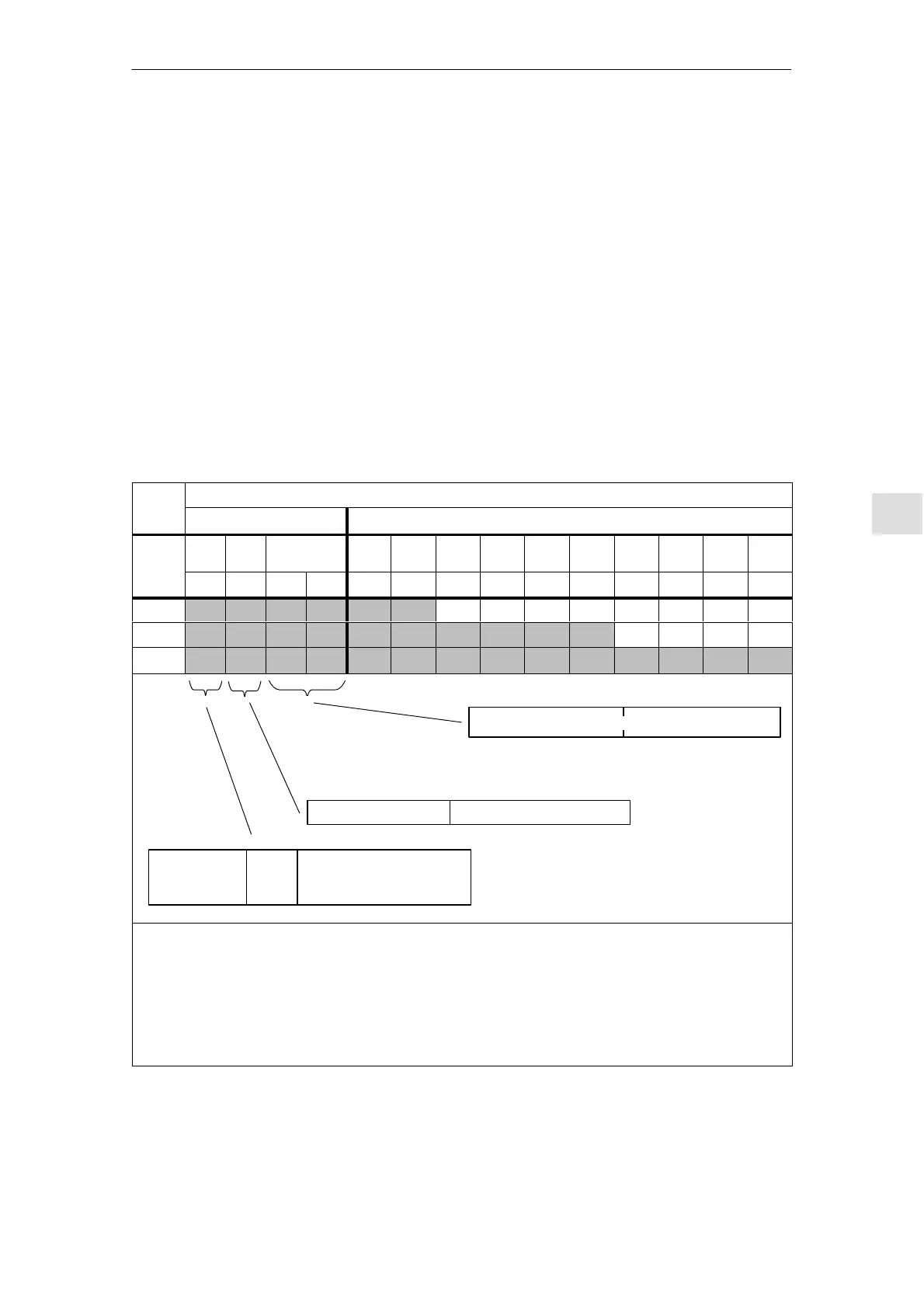
Table 5-28 Structure of the parameter area (PKW)
Net data
PKW PZD
PKE IND PWE
PZD
1
PZD
2
PZD
3
PZD
4
PZD
5
PZD
6
PZD
7
PZD
8
PZD
9
PZD
10
Word 1 2 3 4 1 2 3 4 5 6 7 8 9 10
PPO1
PPO2
PPO5
PNU
Value range 1 ...1 999
Sub–parameter number
AK
Value range
0 ... 15
re–
served
Bit 15 ... 12 11 10 ... 0
Bit 15 ... 8 Bit 7 ... 0
Bit 15 ... 0 Bit 15 ... 0
Word 3 Word 4
Reserved
Value with the appropriate data type
16–bit parameters: Value = 0 Value
32–bit parameters: High component Low component
Note:
refer to P0879.11
(Sub–index in the high/low byte of IND)
Abbreviations:
PPO Parameter Process data Object
PKW Parameter ID value
PZD Process data
PKE Parameter ID
IND Sub–index,
sub–parameter number, array index
PWE Parameter value
AK Task and response ID
(refer to Table 5-29 or 5-30)
PNU Parameter number
Tasks
Structure of the
PKW area
5 Communications via PROFIBUS DP
04.99