2
2.2 Connecting–up
2-70
Siemens AG 2005 All Rights Reserved
SIMODRIVE 611 universal Description of Functions (FBU) – 04.05 Edition
2.2.3 Connecting–up the power module
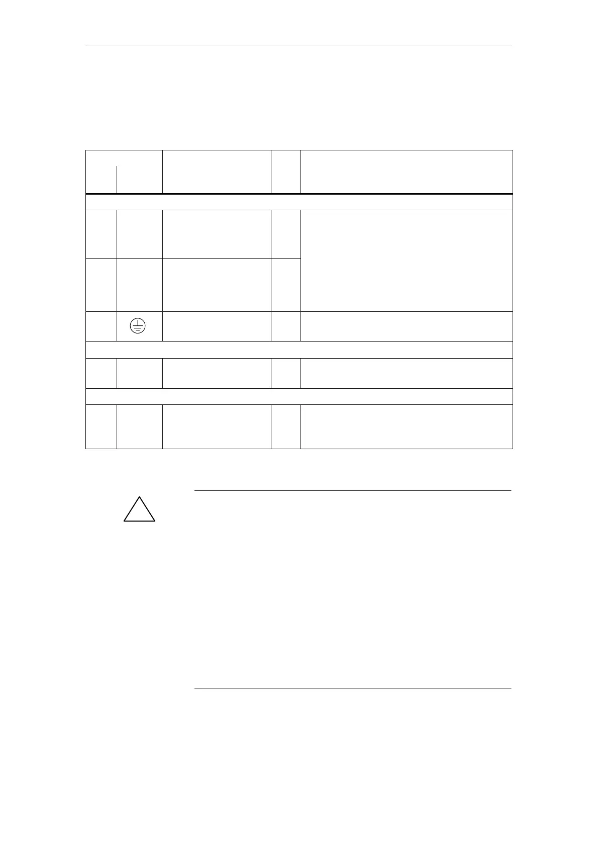
Table 2-2 Overview of the interfaces
Terminals
Function Type
Technical data
No. Desig-
nation
Motor connections
U2
V2
W2
A1 Motor connection
for drive A
O Note:
Additional information on connecting–up the powe
module, technical data as well as interface over-
view are included in:
U2
V2
W2
A2 Motor connection
for drive B
(only for 2–axis
power modules)
O
Reference: /PJU/ SIMODRIVE 611
Configuration Manual,
Drive Converters
Chapter ”Power module”
PE Protective conductor I 0 V
Screw
DC link
P600
M600
– DC link IO Busbar
Equipment bus
– X151 Equipment bus IO Ribbon cable: 34–pole
Voltages: various
Signals: various
1) O: Output; I: Input; IO: Input/output
!
Warning
If a contactor is used between the motor and the power module, then it
must be ensured that this contactor is only switched in a no–current
condition (power circuit).
Powering–down:
When terminal 663 (pulse cancellation) is simultaneously de–energized
and the coil of the power contactor, this condition is maintained. The
pulses are almost instantaneously canceled, the contactor contacts are
then in a no–current condition, and switch somewhat later due to the
contact delay.
Powering–up:
Terminal 663 may only be energized if all of the main contacts of the
power contactor are closed (e.g. terminal 663 is switched through an
auxiliary contact of the power contactor).
2 Installing and Connecting-Up