5
5.6 Net data (PKW and PZD area)
5-243
Siemens AG 2005 All Rights Reserved
SIMODRIVE 611 universal Description of Functions (FBU) – 04.05 Edition
5.6.4 Encoder interface (n–set mode, from SW 3.1)
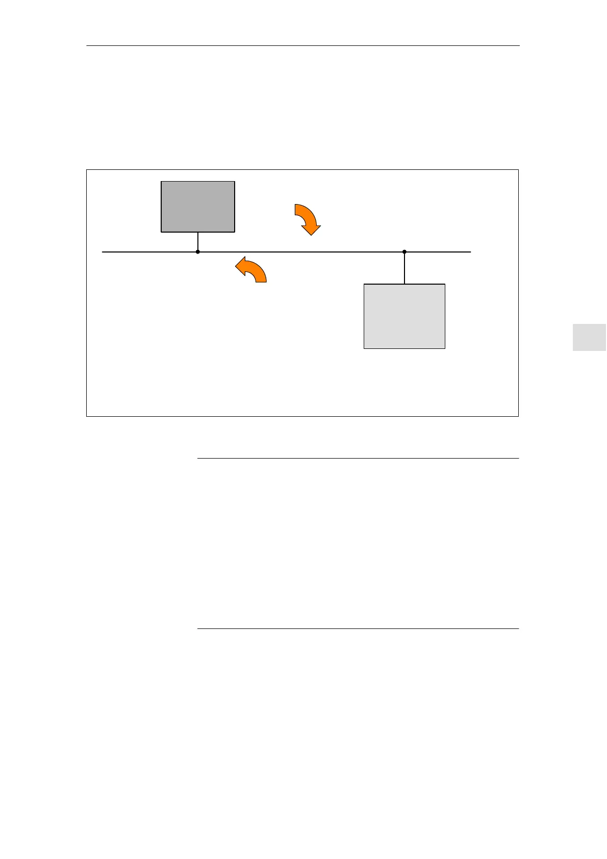
The encoder interface comprises the following process data:
DP master
DP slave
611U
G1_STW
G2_STW
G3_STW
G1_ZSW G1_XIST1 G1_XIST2
G2_ZSW G2_XIST1 G2_XIST2
G3_ZSW G3_XIST1 G3_XIST2
Note:
G1_ ... Encoder 1 ––> Motor encoder Drives A, B: X411, X412
G2_ ... Encoder 2 ––> Direct meas. system Only drive A: X412 (from SW 3.3)
G3_ ... Encoder 3 ––> Additional meas. system X472 (only for ”SIMODRIVE 611 universal E
Control
signals
Status signals
Fig. 5-13 Process data of the encoder interface
Note
The process data of the encoder interface can be included in the
telegram when configuring the process data.
––> Refer to Chapter 5.6.5
– Encoder 1: Standard telegram 3 or 102 (refer to P0922)
– Encoder 2: Standard telegram 103 (refer to P0922)
– Enc. 1 and 3: Standard telegram 104 (refer to P0922)
The process data for encoder 2 must be activated via P0879.12.
The description of this process data can be taken from the following
literature:
Reference: /PPA/, PROFIdrive Profile Drive Technology
Encoder interface
process data
5 Communications via PROFIBUS DP
05.00