2
2.3 Connection diagram and wiring
2-78
Siemens AG 2005 All Rights Reserved
SIMODRIVE 611 universal Description of Functions (FBU) – 04.05 Edition
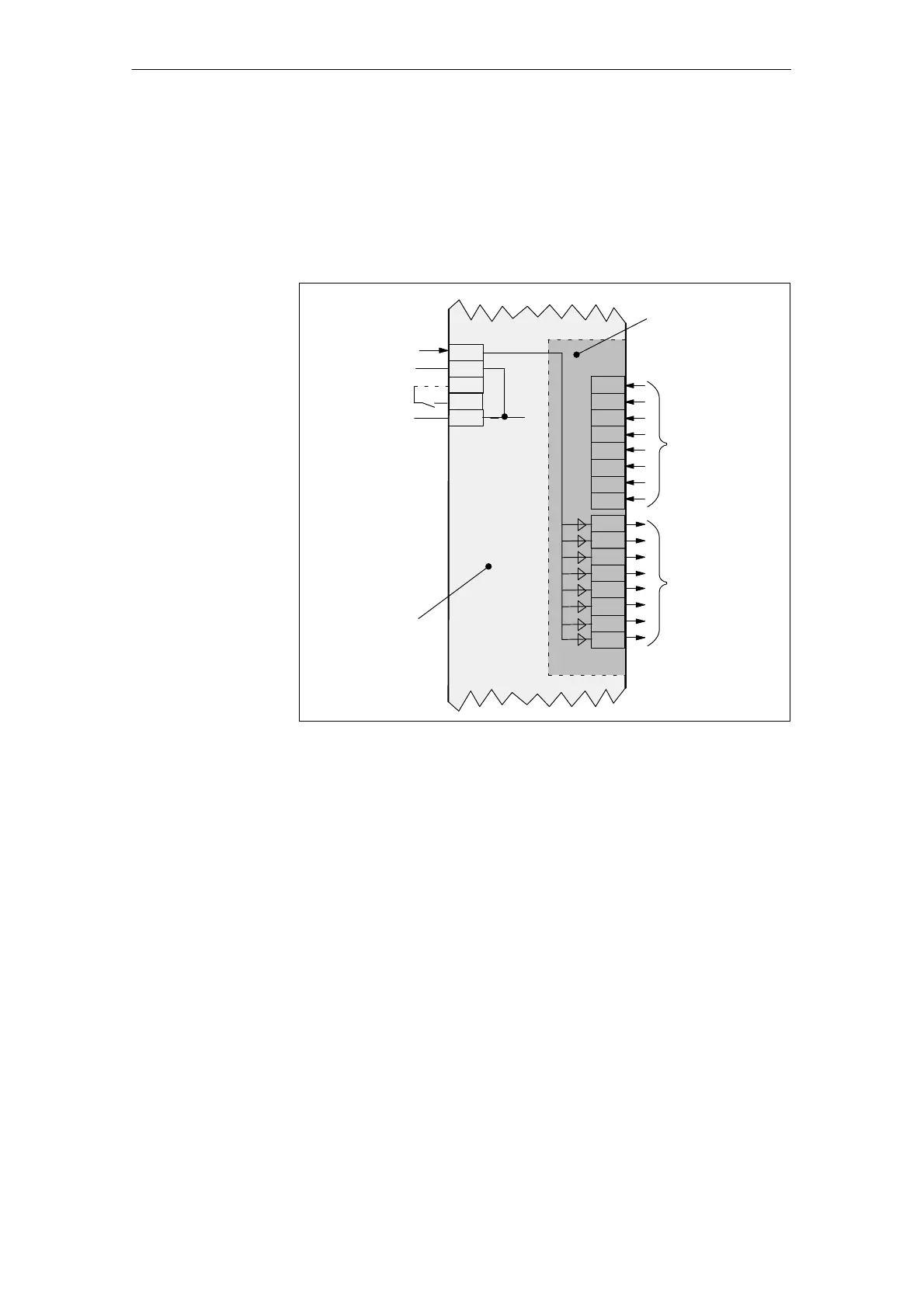
2.3.3 Connection diagram, connecting–up the optional TERMINAL
module
IF
FR+
Digital
inputs
(I: Input)
Digital
outputs
(O: Output)
External
supply
External
reference
FR–
Control board
Optional
TERMINAL
module
external
I6
I7
I8
I5
I4
I9
I10
I11
X422
X432
9
19
M24
P24
663
X431
O6
O7
O8
O5
O4
O9
O10
O11
internal
Fig. 2-7 Connection diagram for the optional TERMINAL module
Connection
diagram for the
optional
TERMINAL module
2 Installing and Connecting-Up