6
6.1 Operating mode, speed/torque setpoint (P0700 = 1)
6-335
Siemens AG 2005 All Rights Reserved
SIMODRIVE 611 universal Description of Functions (FBU) – 04.05 Edition
For the ramp–function generator, the following signals are used:
Input signal – Ramp–function generator enable
– Ramp–up time zero
– Ramp–up time zero for contr. enable (from SW 3.1)
Output signal – Ramp–up completed
Reader’s note
The signals can be entered or output as follows:
via terminals ––> refer to Chapter 6.4.2 or 6.4.5
via PROFIBUS–DP ––> refer to Chapter 5.6.1
All of the input/output signals are shown and described in Chapter
6.4.3 and 6.4.6 and can be found in the Index under ”Input signal...” or
”Output signal...”.
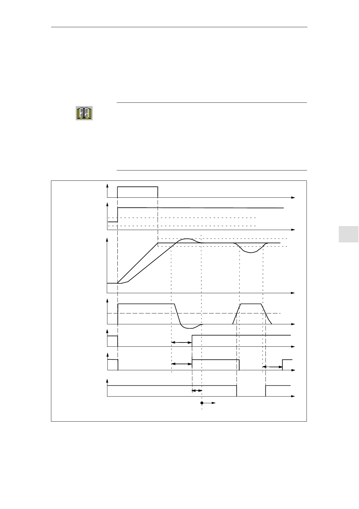
Ramp–function
generation
active
n
set
Tolerance bandwidth P1426
Ramp–up
completed
| M | < M
x
n
set
n
act
Threshold P1428
Torque
Delay time P1427
Delay time P1429
P1427
P1427
n
set
= n
act
RFG input
RFG output
P1426
from here onwards, | M | < Mx evaluation
1) For an active average–value filter for the speed setpoint (P1012.8=1), a setpoint step somewhat
greater than P1426 must be used in order to clearly identify the start of a new ramp–up operation.
Fig. 6-5 Signal characteristics for the ramp–function generator
Input/output
signals for the
ramp–function
generator
6 Description of the Functions
07.03
 Loading...


