6
6.4 Input/output terminals of the control board
6-499
Siemens AG 2005 All Rights Reserved
SIMODRIVE 611 universal Description of Functions (FBU) – 04.05 Edition
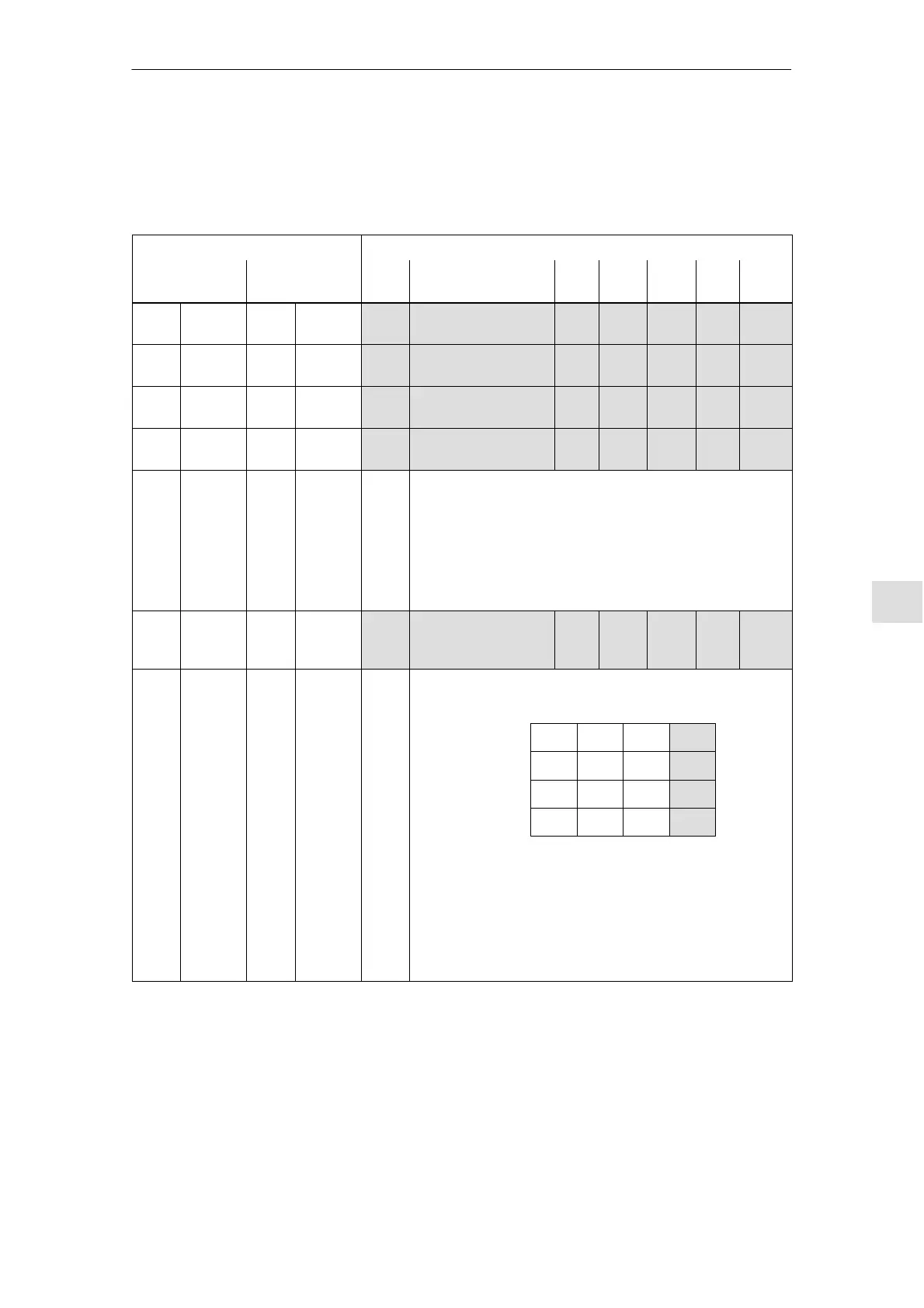
There is the following assignment between terminals, drives and para-
meters:
Table 6-47 Overview for freely–parameterizable output terminals
Terminals
Parameters
Drive A Drive B No. Name Min. Stan-
dard
Max. Unit
s
Effec-
tive
O0.A X461.7 O0.B X462.7 0680 Signaling function,
output terminal O0.x
0 33 82 – Imme-
diately
O1.A X461.8 O1.B X462.8 0681 Signaling function,
output terminal O1.x
0 2 82 – Imme-
diately
O2.A X462.9 O2.B X462.B 0682 Signaling function,
output terminal O2.x
0 1 82 – Imme-
diately
O3.A X461.10 O3.B X462.10 0683 Signaling function,
output terminal O3.x
0 5 82 – Imme-
diately
– – – – A function can be assigned to each output terminal using
these parameters.
The function number from the list of output signals is en-
tered (refer to Chapter 6.4.6).
Note:
The status of the output terminals is displayed in P0698 for
diagnostics (refer to Chapter 4.5).
– – – – 0699 Inversion
Output terminal sig-
nals
0 0 FFF hex Imme-
diately
– – – – The output terminal signals can be inverted using this pa-
rameter.
2
0
= 1
2
1
= 2
2
2
= 4
2
3
= 8
P0699 = 0 5 0 6 hex
––> O8 O1.x
O10 O2.x
are output inverted
O0.x:
O1.x:
O2.x:
O3.x:
O4
O5
O6
O7
O8
O9
O10
O11
res.
res.
res.
res.
Example:
Note:
O4 – O11 are available on the optional TERMINAL module
(refer to Chapter 6.5).
Overview of the
terminals and
parameters
6 Description of the Functions