6
6.5 Input/output terminals for the optional TERMINAL module
6-527
Siemens AG 2005 All Rights Reserved
SIMODRIVE 611 universal Description of Functions (FBU) – 04.05 Edition
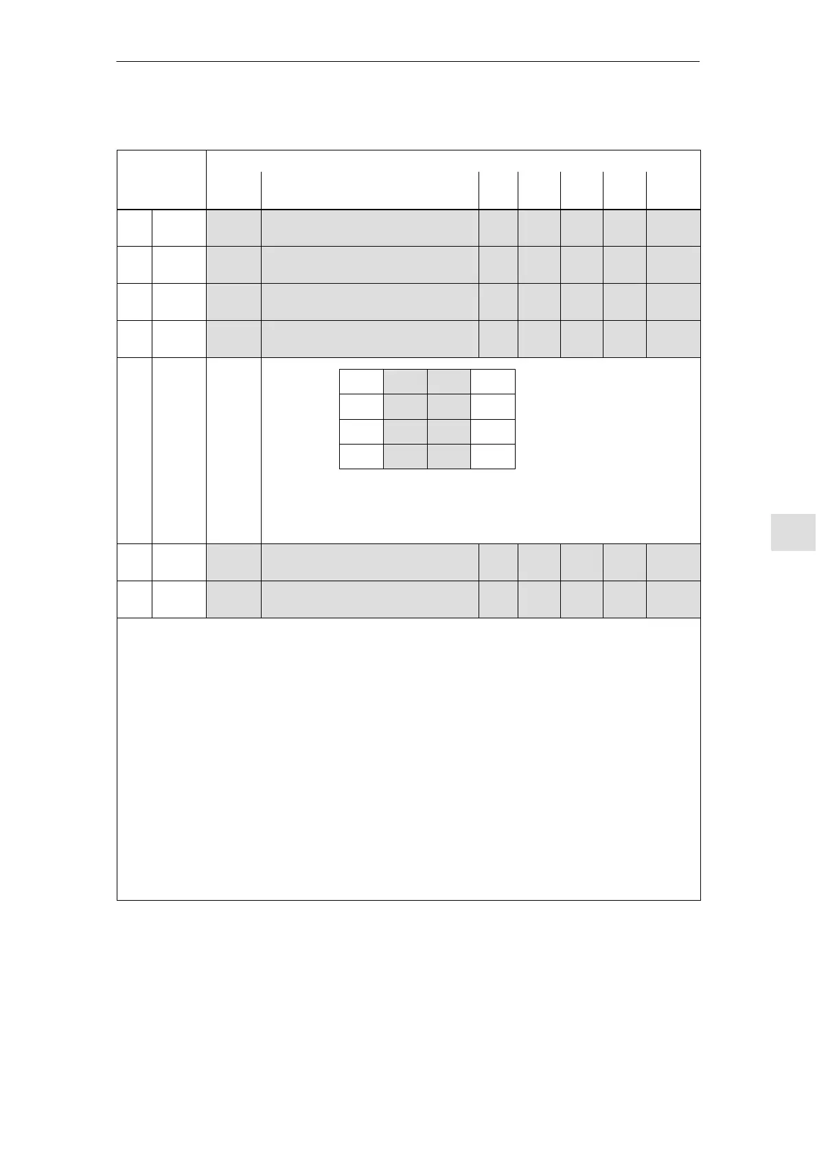
Table 6-50 Terminals and parameters for the optional TERMINAL module, continued
Terminals Parameters
Drive A/B Effec-
tive
UnitsMax.Stan-
dard
Min.NameNo.
O9 X432.6 0689 Signaling function
output terminal O9
0 52 82 – Immed.
O10 X432.7 0690 Signaling function
output terminal O10
0 53 82 – Immed.
O11 X432.8 0691 Signaling function
output terminal O11
0 54 82 – Immed.
– – 0699 Inverting the
output terminal signals
0 0 FFF hex Immed.
2
0
= 1
2
1
= 2
2
2
= 4
2
3
= 8
P0699 = 0 5 0 6 hex
––> O8 O1.x
Example: O10 O2.x
are output inverted
O0.x:
O1.x:
O2.x:
O3.x:
O4
O5
O6
O7
O8
O9
O10
O11
res.
res.
res.
res.
O0.x – O3.x are available
on the control board (refer
to Chapter 6.4.5)
– – 0676 Assignment, inputs of the optional
TERMINAL module (from SW 4.1)
0 0 3 – Immed.
– – 0696 Assignment, outputs optional TERMI-
NAL module (from SW 4.1)
0 0 3 – Immed.
Each input/output terminal can be assigned a function using these parameters.
Note:
Input terminals:
The function number from the list of input signals is entered (refer to Chapter 6.4.3).
The status of the input terminals is displayed in P0678 for diagnostic purposes (refer to Chapter 4.5).
Output terminals:
The function number from the list of output signals is entered (refer to Chapter 6.4.6).
The status of the output terminals is displayed in P0698 for diagnostics (refer to Chapter 4.5).
The signals of the output terminals can be output inverted (P0699).
Assignment of the terminals:
Before SW 4.1 the following applies:
All of the input/output terminals for the optional TERMINAL module are permanently assigned drive A.
From SW 4.1, the following applies:
For a double–axis module, the input/output terminals can be assigned, blockwise to either drive A or
B (P0676, P0696).
6 Description of the Functions
02.02