2
2.2 Connecting–up
2-68
Siemens AG 2005 All Rights Reserved
SIMODRIVE 611 universal Description of Functions (FBU) – 04.05 Edition
The following cables are recommended when connecting–up the most
important terminals on the control board:
Table 2-1 Recommended cable
Cable
for
Description Order No. (MLFB)
Analog
inputs
Term. 56.A/14.A cond. 2 2 0.38 mm
2
Term. 24.A/20.A cond. 2 2 0.38 mm
2
Note:
4–conductor connection, e.g. at drive A
6FX2008–1BD21–
Cable, sold by the
meter,
twisted pairs with
overall shield
Conductors:
4 2 0.38 mm
2
+
4 0.5 mm
2
Analog
outputs
Term. 75.A/15 conductor 2 0.5 mm
2
Term. 16.A/15 conductor 2 0.5 mm
2
Angular
incre-
mental
en-
coder
inter-
face
Term. A+.A conductor 1 0.38 mm
2
Term. A–.A conductor 1 0.38 mm
2
Term. B+.A conductor 1 0.38 mm
2
Term. B–.A conductor 1 0.38 mm
2
Term. R+.A conductor 1 0.38 mm
2
Term. R–.A conductor 1 0.38 mm
2
Terminal 15
(from SW 5.1) conductor 1 0.38 mm
2
6FX2008–1BD21–
Cable, sold by the me-
ter,
twisted pairs with over-
all shield
Conductors:
4 2 0.38 mm
2
+
4 0.5 mm
2
Remaining: Conductor 1 0.38 mm
2
+ 4
0.5 mm
2
Input/
output
termi-
nals
Term. I0.x to term. I3.x
Term. O0.x to term. O3.x
Term. I4 to term. I11
Term. O4 to term. O11
50–conductor cable
without overall shield
Conductors: 50 0.38
mm
2
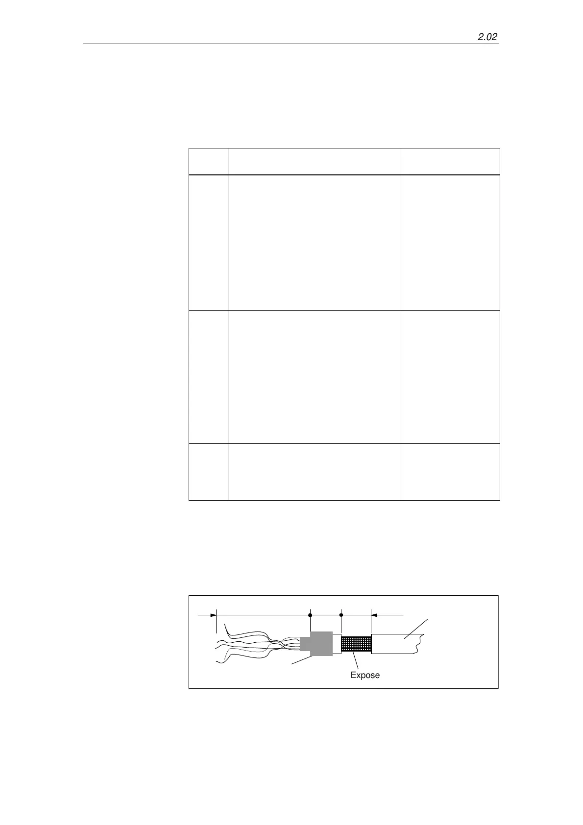
To connect the shield to the side of the power module, the cable end
must be prepared as illustrated in Fig. 2-5.
With the shield exposed, the cable is connected at the top of the power
module using a shield connecting terminal (tapped holes are provided).
Exposed shield
Cable sheath
Shrink tubing
Approx. 300 Approx. 15
Approx. 15
not
to scale
Fig. 2-5 Preparing the cable end for the shield connection
Recommended
cable
Shield connection
to the side of the
power module
2 Installing and Connecting-Up
02.02