2
2.3 Connection diagram and wiring
2-81
Siemens AG 2005 All Rights Reserved
SIMODRIVE 611 universal Description of Functions (FBU) – 04.05 Edition
The following bus connectors can be connected to the optional
PROFIBUS–DP module:
Bus connector for copper cable (e.g.: Cable 6XV1 830–0AH10)
Order No. (MLFB): 6ES7 972–0BB40–0XA0 (with PG connection)
Order No. (MLFB): 6ES7 972–0BA40–0XA0 (without PG connec-
tion)
The following bus connectors are permissible for copper cable:
Order No. (MLFB): 6FX2 003–0AA03 (with PG connection)
Order No. (MLFB): 6FX2 003–0AA02 (without PG connection)
Order No. (MLFB): 6GK1 500–0EA00 (axial cable outlet)
OLP (optical link plug)
Bus connector for fiber–optic cables (baud rate: max. 1.5 Mbaud)
Order No. (MLFB): 6GK1 502–1AA00
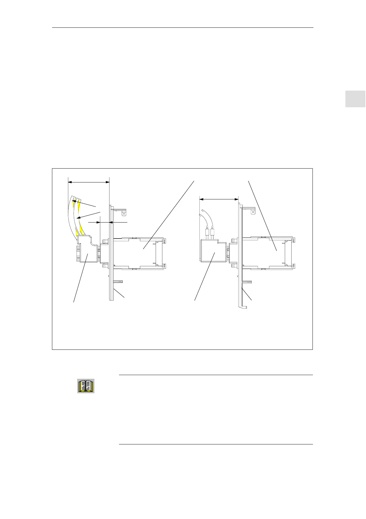
80.1 (348)
74.9 (343)
R86
R75
18
Optional PROFIBUS–DP module
Bus connector for copper
cables (with PG connection)
OLP (optical link plug)
Bus connector for fiber–optic cables
Note:
The dimensions in brackets specify the total depth up to the rear cabinet panel.
The external shield should be connected through the largest possible surface area (refer to Fig. 2-5).
Front panel
Front panel
Fig. 2-9 Mounting depth of the bus connector for the optional PROFIBUS–DP module
Reader’s note
Additional information on configuring a PROFIBUS–DP network is
provided in:
References: /IK10/ SIMATIC NET, Industrial communications,
Catalog IK 10
/STPI/ PROFIBUS & AS Interface, Components
Connected to the Field Bus, Catalog ST PI
Bus connector and
mounting
dimensions
2 Installing and Connecting-Up