2
2.4 Pin assignment of the interfaces
2-83
Siemens AG 2005 All Rights Reserved
SIMODRIVE 611 universal Description of Functions (FBU) – 04.05 Edition
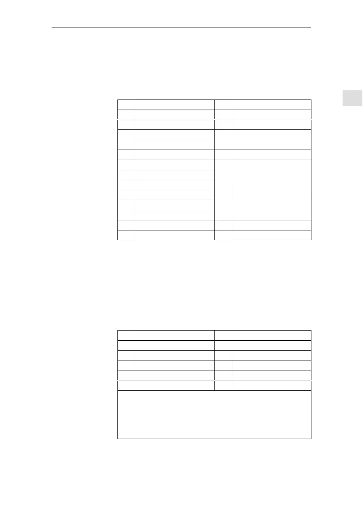
Connector designation: X411 ––> Drive A
X412 ––> Drive B
Connector type: 25–pin, D–Sub, plug connector
Table 2-7 Assignment of X411/X412 for resolvers
Pin
Signal name Pin Signal name
1 Reserved 14 Reserved
2 M_Encoder 15 Reserved
3 SIN_PLUS 16 Reserved
4 SIN_MINUS 17 Reserved
5 Inner shield 18 Reserved
6 COS_PLUS 19 Reserved
7 COS_MINUS 20 Reserved
8 Inner shield 21 Reserved
9 Excitation_Pos 22 Reserved
10 Reserved 23 Reserved
11 Excitation_Neg 24 Inner shield
12 Reserved 25 Temp–
13 Temp+ – –
Cable Order No. (MLFB)
Resolver in the motor 6FX2 002–2CF01–10
: Space retainer for the cable type (length, ...)
References: /Z/ Catalog NC Z, Accessories and Equipment
Connector type: 9–pin, D–Sub socket connector
Table 2-8 Assignment of the serial interface
Pin
Signal name Pin Signal name
1 RS485 DATA+ 6 Reserved
2 RS232 TxD 7 RS232 CTS
3 RS232 RxD 8 RS232 RTS
4 Reserved 9 RS485 DATA–
5 Ground, 0 V – –
Note:
The serial interface can be declared an RS232 or an RS485 interface by
appropriate parameterization (refer to Chapter 3.3.3).
When set as an RS485 interface, a terminating resistor can be switched
in/out via switch S1 on the front panel.
The cable diagrams for the serial interface are provided in Chapter 2.5.
Pin assignment of
X411/X412 for the
control board for
resolvers
Serial
interface
X471
2 Installing and Connecting-Up