2
2.5 Cable diagrams
2-86
Siemens AG 2005 All Rights Reserved
SIMODRIVE 611 universal Description of Functions (FBU) – 04.05 Edition
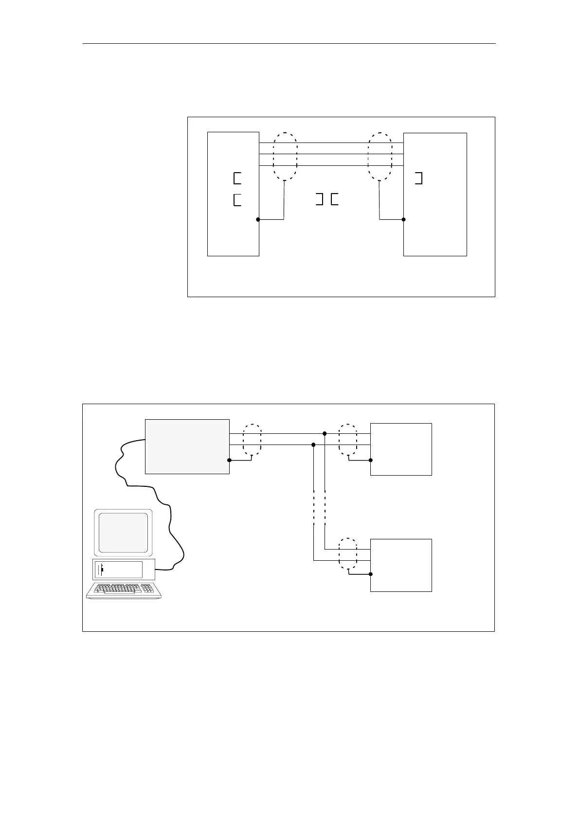
Cable diagram: 25/9 conductor
SIMODRIVE 611 universalPG
RxD 3
TxD 2
0 V 7
RTS 4
CTS 5
DSR 6
DTR 20
1
2 TxD
3 RxD
50 V
7 CTS
8RTS
Connection at X471Connection to a
serial interface
e.g. COM1 V24/AG for PG
25–pin
D–Sub
plug con.
9–pin
D–Sub
plug con.
0.1 mm
2
Setting the interface to
RS232 (P0801 = 0)
Jumpered in the
connector
Remove the latch
interlock on the
SIMODRIVE side
Fig. 2-12 RS232 connecting cable: PG <–> SIMODRIVE 611 universal
Order no.: 6FC9 348–2T00 = B ––> Length 5 m
= C ––> Length 10 m
SIMODRIVE 611 universal
Note:
Pins which are not used
may not be assigned.
Connection at X471
9–pin
D–sub, plug
0.1 mm
2
1 (data +)
9 (data –)
RS232/RS485
interface
converter
First
node
SIMODRIVE 611 universal
Connection at X471
9–pin
D–sub, plug
1 (data +)
9 (data –)
n–th
node
RS232
RS485
PG/PC
RS485
Setting the interface to
RS485 (P0801 = 1)
Setting the interface to
RS485 (P0801 = 1)
Fig. 2-13 RS485 connecting cable:
PG/PC <––> RS232/RS485 interface converter <––> SIMODRIVE 611 universal
Cable diagram for
RS485
2 Installing and Connecting-Up
04.99