Configuration
5.4 Installation
1FW6 Built-in torque motors
114 Configuration Manual, 07/2017, 6SN1197-0AE00-0BP9
Both motors are suitable for this positioning task. The installation requirements govern which
motor is better suited. During positioning, the motor reaches a torque that far exceeds its
rated torque M
N
, and the resulting power loss is much greater than the permissible
continuous power loss. Provided that positioning only takes a short time and the winding
temperature remains below the shutdown limit, this high load is permissible. Also see
Section "Intermittent duty S3" in Chapter "Specification of the duty cycle".
Periodic duty cycle (S3 mode)
The motor can repeat a drive operation any number of times (e.g. the positioning operation
described above), in which M > M
N
intermittently occurs, if there are sufficiently long intervals
in which the windings are de-energized between the load phases. Also see Section
"Intermittent duty S3" in Chapter "Specification of the duty cycle."
The "duty cycle" comprises the load phase and the zero-current (cooling) phase. The cooling
phases are crucial here: As a result of the no-load intervals, the effective torque of the duty
cycle is reduced to the value of the rated torque M
N
of the motor.
If the future duty cycle is either not known or cannot be estimated, the motor can only be
selected on the basis of the required maximum speed and peak torque. This means that for
the duty cycle, the maximum permissible rms torque M
eff
of the duty cycle is also defined.
This results in a very short cooling phase, the length of which must not be undershot.
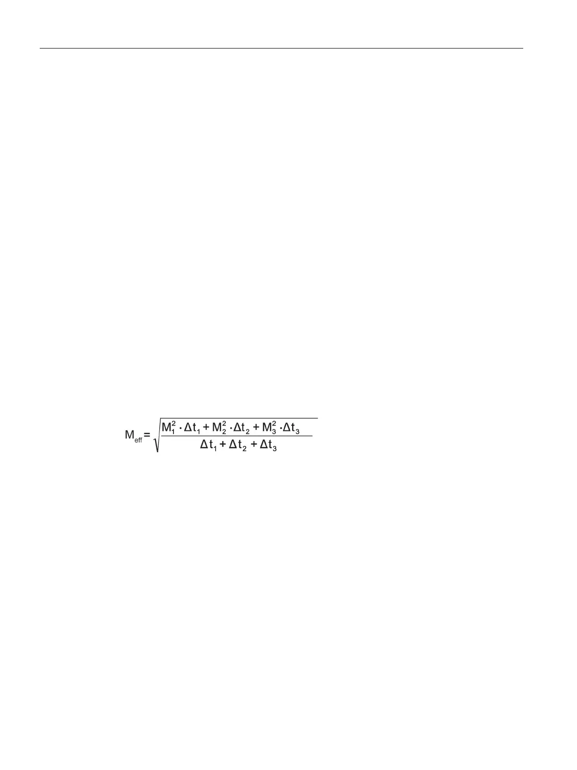
A significantly simplified load cycle comprising three time segments with lengths Δt
1
, Δt
2
, Δt
3
is assumed by way of example. In these time segments, torques M
1
, M
2
, M
3
are produced.
Each of these torques can have any value between + M
MAX
and – M
MAX
. The effective torque
M
eff
of this load cycle in Nm can be calculated using the following formula:
In this case, the cycle duration (Δt
1
+ Δt
2
+ Δt
3
) should not be longer than 10 % of the
thermal time constant t
TH
.
The load cycle is permissible, as long as M
eff
≤ M
N
.

 Loading...


