Installation drawings/Dimension drawings
9.2 Information on the installation drawings
1FW6 Built-in torque motors
Configuration Manual, 07/2017, 6SN1197-0AE00-0BP9
521
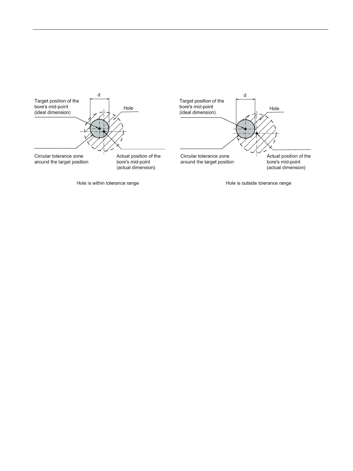
The schematic representation below shows the position tolerance for fastening holes
according to DIN EN ISO 1101:2008-08. The diameter "d" of the circular tolerance zone
indicates the tolerance.
Figure 9-3 Position tolerance for fastening holes
The actual position of the hole's mid-point (actual dimension) must lie within the circular
tolerance zone to enable the motor components to be attached without any problems. If no
specific value has been stated, the standard tolerance of d = 0.2 mm (as used by the
machine tool industry) applies.

 Loading...


