Infeed
2.1 Active Infeed
Drive functions
34 Function Manual, 11/2017, 6SL3097-4AB00-0BP5
Operating mode of Active Infeed closed-loop control for Active Line Modules chassis.
Active Line Modules chassis only function in Active Mode.
In the Active Mode, the DC link voltage is regulated to a variable setpoint (p3510) which
results in a sinusoidal line current (cos φ = 1).
The DC link voltage setpoint (p3510) is preset depending on the supply voltage (p0210)
using the equation p3510 = 1.5 · p0210.
The device supply voltage (p0210) must be parameterized during commissioning. The
necessary line filter (p0220) is preset.
When it is first switched on with a new/modified network, an automatic controller setting
should be implemented using the line / DC link identification routine (p3410).
While the identification routine is running, it is not permissible that other loads are switched-
in/switched-out.
Note
In a supply system without regenerative feedback capability (e.g. generators), regenerative
operation must be inhibited via the binector input p3533.
The DC link voltage (p3510) can be set within the following limits:
● Upper limit:
– Maximum DC link voltage (p0280)
– Product of the supply voltage (p0210) and step-up factor (max. p3508 = 2.00)
● Lower limit: Supply voltage (p0210) multiplied by 1.42
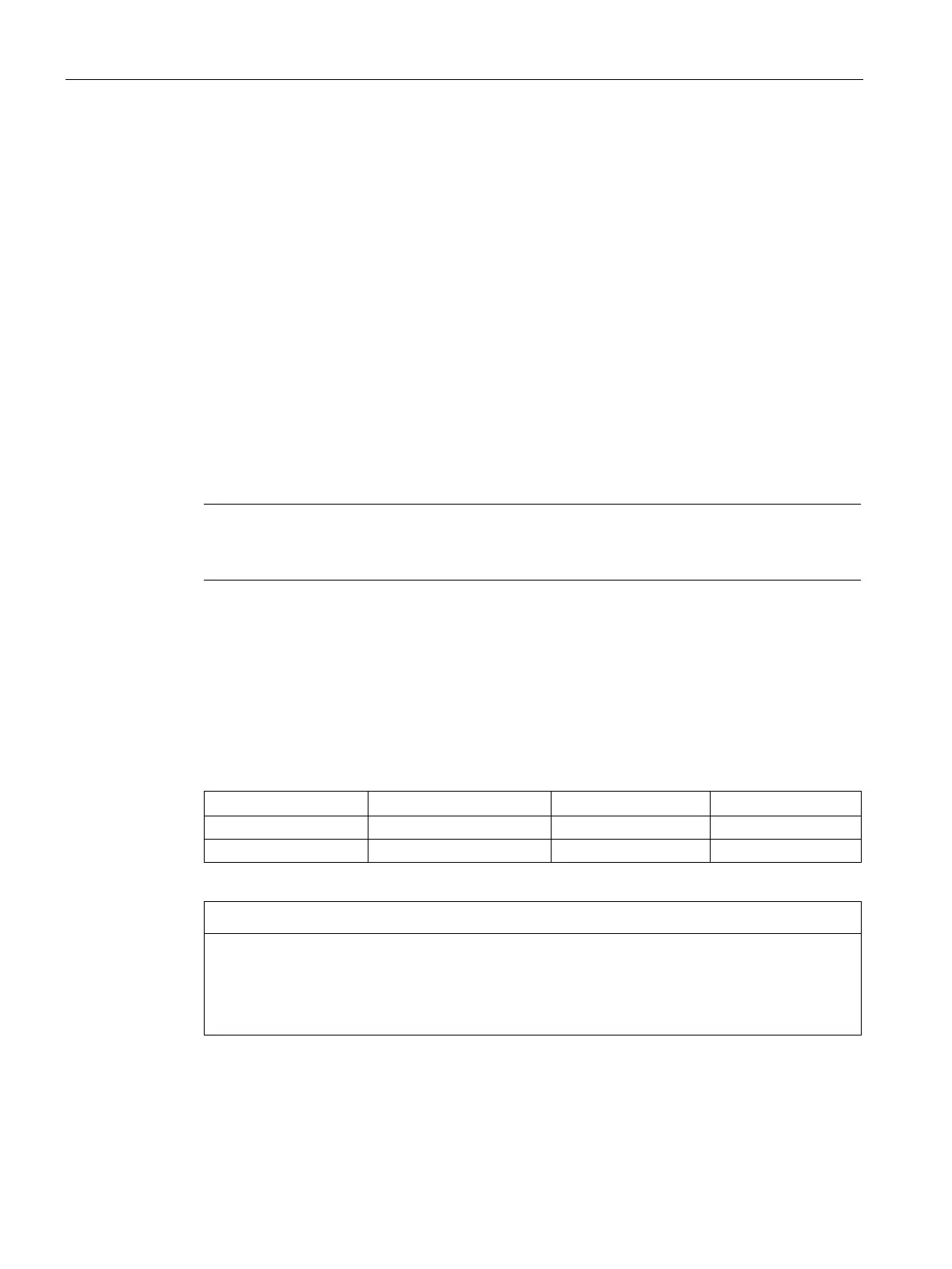
For the DC link voltage, the following values apply for chassis units (p0280):
Overheating of the components
An excessively high step-up factor for Active Line Modules Chassis can overheat and
destroy components.
• Set the step-up factor to a maximum value of 2.00.

 Loading...


