Basic functions
7.13 Motor Module as a Braking Module
Drive functions
354 Function Manual, 11/2017, 6SL3097-4AB00-0BP5
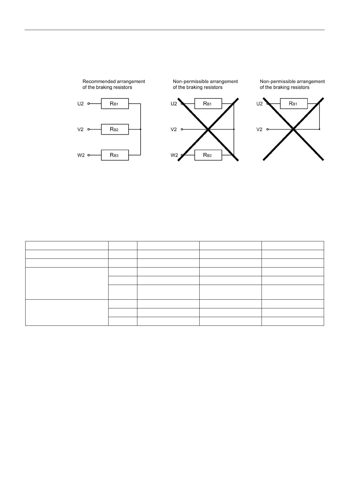
Connecting braking resistors
Preferably connect the braking resistors in a star configuration
Figure 7-5 Braking resistors
Setting of the Braking Module activation threshold
The value of the Braking Module activation threshold p1362[0] and the hysteresis p1362[1]
can be adjusted. Depending on the voltage type, the parameters are assigned different
values depending on the factory setting of p0210.
Table 7- 10 Activation threshold
U
DC link
Braking Module activation
threshold
min
V
max
789 986 1179
HW shutdown threshold
rated
Activating the "Braking Module" function
You have opened the STARTER commissioning tool and created a new project or opened
an existing project.
Activating the Braking Module
1. Configure the Control Unit and the infeed module as usual (see SINAMICS S120
Commissioning Manual with STARTER).
2. Select "Vector" as drive object type.

 Loading...


