Communication
11.6 Communication via SINAMICS Link
Drive functions
898 Function Manual, 11/2017, 6SL3097-4AB00-0BP5
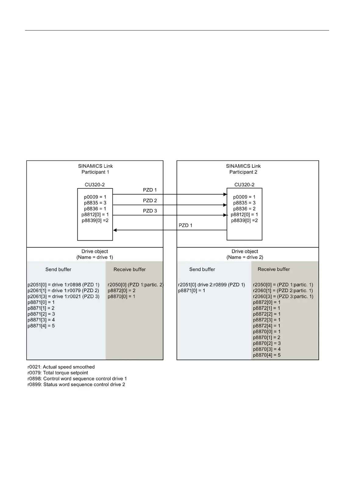
11.Define the receive data for node 1:
– Specify the data that should be placed in the receive buffer p8872 of node 1 in
location 0, received from node 2:
p8872[0] = 2
– Define that PZD1 of node 2 is saved in the receive buffer p8870 of node 1 in location
0:
p8870 [ 0] = 1
– r2050[0] subsequently contains (after step 13) the value of PZD 1 of node 2.
12.At the two nodes carry-out a "Copy RAM to ROM" to backup the parameterization and the
data.
13.Set p8842 =1, to activate parameters p8870, p8871 and p8872.
Figure 11-52 SINAMICS Link: Configuration example

 Loading...


