Coordinate transformation (FRAMES)
5.1 Coordinate transformation via frame variables
Job planning
Programming Manual, 07/2010, 6FC5398-2BP40-0BA0
285
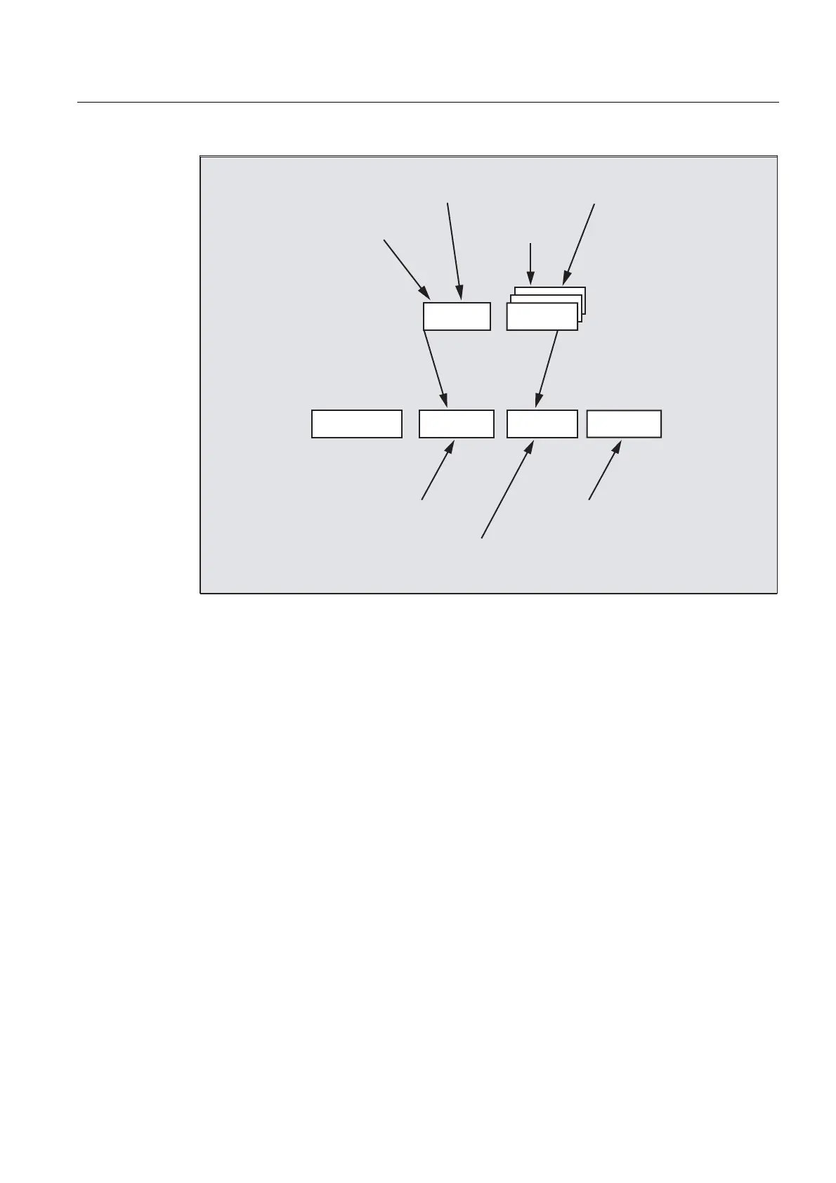
3B3)5$0(
3B8,)5>Q@3B8%)5
3B$&7)5$0( 3B%)5$0( 3B,)5$0(
,QSXWIURPSURJUDPHJ
3B3)5$0( &75$16;
RU75$16;
,QSXWIURPSURJUDPHJ
3B,)5$0( &75$16;
,QSXWIURPSURJUDPHJ
3B%)5$0( &75$16;
,QSXWIURPSURJUDPHJ
3B8,)5>Q@ &75$16;
,QSXWIURP
+0,00&
,QSXWIURPSURJUDPHJ
3B8%)5 &75$16;
,QSXWIURP
+0,00&
DFWLYDWHGYLD
***
Basic frame and settable frame are effective after Reset if MD 20110 RESET_MODE_MASK
is set as follows:
Bit0=1, bit14=1 -->
$P_UBFR (basic frame) acts
Bit0=1, bit5=1 -->
$P_UIFR [$P_UIFRNUM](settable frame) acts
Predefined settable frames $P_UBFR
The basic frame is programmed with $P_UBFR, but it is not simultaneously active in the
parts program. The basic frame programmed with $P_UBFR is included in the calculation if
● Reset was activated and bits 0 and 14 are set in MD RESET_MODE_MASK and
● the statements
G500,G54...G599 were executed.
Predefined settable frames $P_UIFR[n]
The predefined frame variable $P_UIFR[n] can be used to read or write the settable zero
offsets
G54 to G599 from the parts program.
These variables produce a one-dimensional array of type FRAME called
$P_UIFR[n].

 Loading...


