Tool offsets
7.5 Activate 3D tool offsets (CUT3DC..., CUT3DF...)
Job planning
Programming Manual, 07/2010, 6FC5398-2BP40-0BA0
413
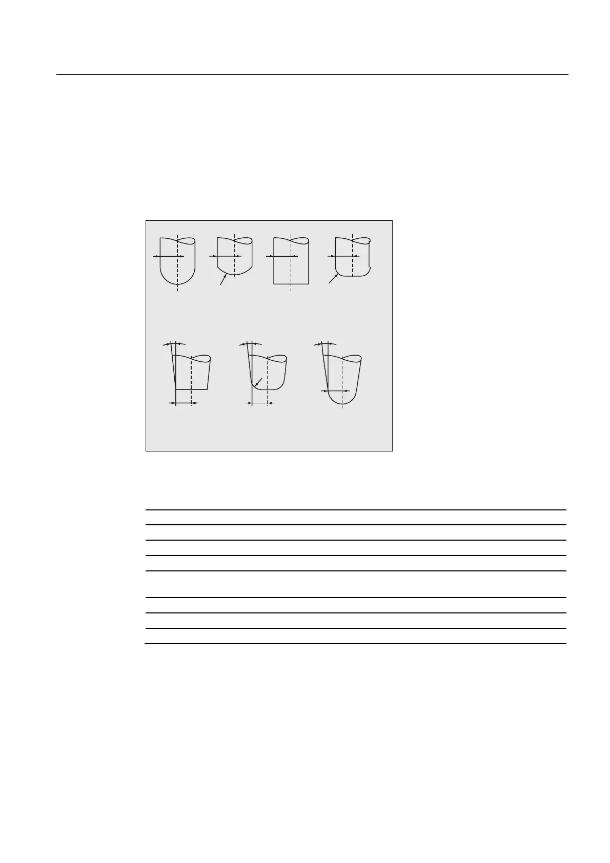
7.5.3 3D tool offset: Tool shapes and tool data for face milling
Mill shapes, tool data
An overview of the tool shapes, which may be used for face milling operations and tool data
limit values are listed in the following. The shape of the tool shaft is not taken into account.
The effect of tool types 120 and 156 is identical.
&\OLQGULFDO
GLHVLQNLQJ
PLOOLQJFXWWHU
W\SH
%DOOHQG
PLOO
W\SH
(QGPLOO
W\SH
(QGPLOOZLWK
FRUQHUURXQGLQJ
W\SH
%HYHOFXWWHU
W\SH
%HYHOFXWWHUZLWK
FRUQHUURXQGLQJ
W\SH
7DSHUHG
GLHVLQNLQJFXWWHU
W\SH
D
5
U
D
5
D
5
U
55
U
5
5
If, in the NC program, a type number is specified that differs from that in the diagram, then
the system automatically uses tool type 110 (cylindrical die-sinking milling tool). An alarm is
output if the tool data limit values are violated.
Cutter type Type No. R r a
Cylindrical die-sinking milling cutter 110 > 0 - -
Ball end mill 111 > 0 > R -
End mill, angle head cutter 120, 130 > 0 - -
End mill, angle head cutter with corner
rounding
121, 131 > r > 0 -
Bevel cutter 155 > 0 - > 0
Bevel cutter with corner rounding 156 > 0 > 0 > 0
Tapered die-sinking cutter 157 > 0 - > 0
R = shaft radius (tool radius)
r = corner radius
a = angle between the tool longitudinal axis and upper end of the torus surface
- = is not evaluated

 Loading...


