Tool offsets
7.5 Activate 3D tool offsets (CUT3DC..., CUT3DF...)
Job planning
414 Programming Manual, 07/2010, 6FC5398-2BP40-0BA0
Tool data Tool parameters
Tool dimensions Geometry Wear
R $TC_DP6 $TC_DP15
r $TC_DP7 $TC_DP16
a $TC_DP11 $TC_DP20
Tool length offset
The tool tip is the reference point for length offset (intersection longitudinal axis/surface).
3D tool offset, tool change
A new tool with modified dimensions (R, r, a) or a different shaft may only be specified with
the programming of
G41 or G42 (transition G40 to G41 or G42, reprogramming of G41 or G42).
This rule does not apply to any other tool data, e.g., tool lengths, so that tools can be loaded
without reprogramming
G41 or G42.
7.5.4 3D tool offset: Compensation on the path, path curvature, insertion depth
(CUT3DC, ISD)
Function
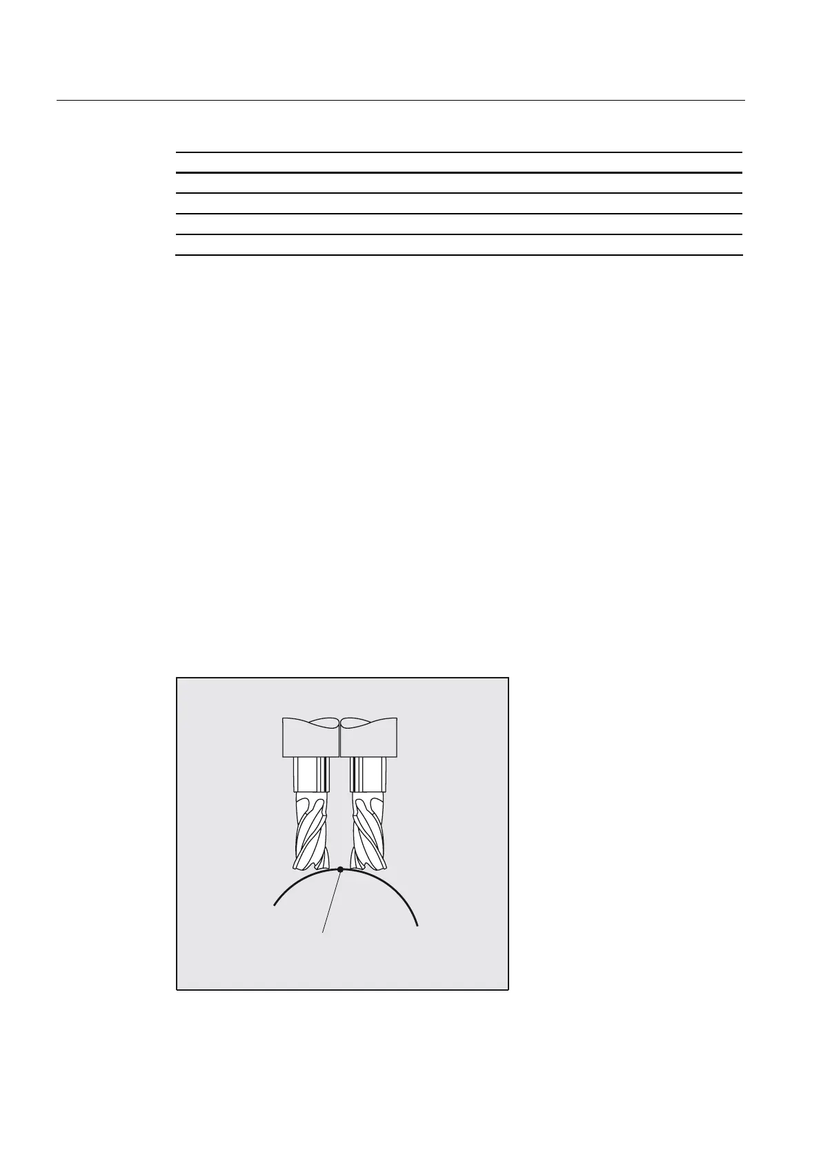
Compensation on path
With respect to face milling, it is advisable to examine what happens when the contact point
"jumps" on the tool surface as shown in the example on the right where a convex surface is
being machined with a vertically positioned tool. The application shown in the example
should be regarded as a borderline case.
6LQJXODUSRLQW

 Loading...


