Tool offsets
7.5 Activate 3D tool offsets (CUT3DC..., CUT3DF...)
Job planning
412 Programming Manual, 07/2010, 6FC5398-2BP40-0BA0
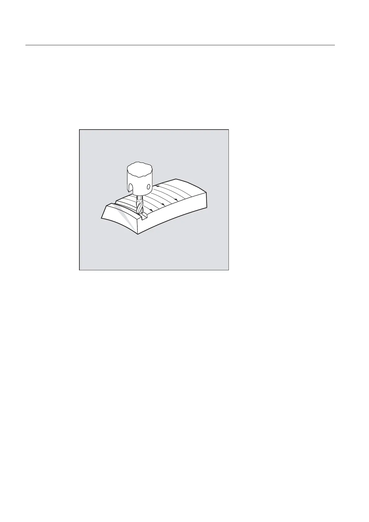
Face milling
For this type of 3D milling, you will require the line-by-line description of the 3D paths on the
workpiece surface. The tool shape and dimensions are taken into account in the calculations
– which are normally performed in CAM. The post processor writes to the part program – in
addition to NC blocks – to orientations (for active 5 axis transformation) and the G code for
the required 3D tool offset. This means that the machine operator has the possibility of using
tools that are slightly smaller – deviating from the tool used to calculate the NC paths.
Example:
NC blocks were computed using a 10 mm milling tool. In this case, a milling tool diameter of
9.9 mm can be used for machining – whereby a modified roughness profile can be
expended.

 Loading...


