Tool offsets
7.5 Activate 3D tool offsets (CUT3DC..., CUT3DF...)
Job planning
416 Programming Manual, 07/2010, 6FC5398-2BP40-0BA0
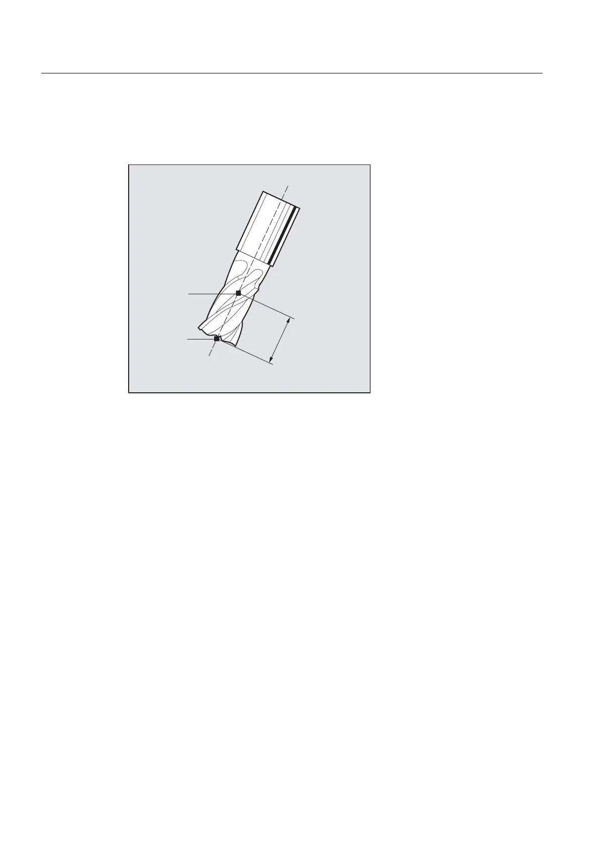
Milling tool reference point
The milling tool reference point (FH) is obtained by projecting the programmed machining
point onto the tool axis.
)6
)+
,6'
Further Information
Pocket milling with inclined side walls for circumferential milling with CUT3DC
In this 3D tool radius compensation, a deviation of the mill radius is compensated by infeed
toward the normals of the surface to be machined. The plane, in which the milling tool face is
located, remains unchanged if the insertion depth
ISD has remained the same. For example,
a milling tool with a smaller radius than a standard tool would not reach the pocket base,
which is also the limitation surface. For automatic tool infeed, this limitation surface must be
known to the control, see section "3D circumferential milling with limitation surfaces".
For additional information on collision monitoring, refer to:
References:
Programming Manual Basics; Chapter "Tool offsets".

 Loading...


