What to do if Siemens Transmitter has a safety critical device error?
- TThomas DuffySep 13, 2025
If the Siemens Transmitter has a safety critical device error, acknowledge the error in menu "Functional Safety" and enable Functional Safety mode.
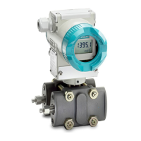
What to do if Siemens Transmitter has a safety critical device error?
If the Siemens Transmitter has a safety critical device error, acknowledge the error in menu "Functional Safety" and enable Functional Safety mode.
| Category | Transmitter |
|---|---|
| Series | SITRANS |
| Measurement Principle | Varies by model (e.g., pressure, temperature, level, flow) |
| Output Signal | HART, PROFIBUS PA, Foundation Fieldbus |
| Temperature Range | Various (depending on the specific model, e.g., -40 to +85 °C) |
| Electrical Connection | others depending on model |
| Protection Class | IP65, IP67 |
| Material | Stainless steel |
| Communication Protocol | HART, PROFIBUS PA, Foundation Fieldbus |
Step-by-step guide for commissioning the device with its display.
Explains the scope and target audience of the manual.
Summarizes changes between manual editions.
Details manual compatibility with device versions and software.
Lists device variants covered by the document.
Outlines essential conditions for safe device operation.
Explains symbols used on the device for safety warnings.
Lists safety rules and regulations applicable to device use.
Details device compliance with European directives (EMC, ATEX, PED).
Advises on contacting Siemens for special ambient conditions.
Provides safety guidelines for operating devices in hazardous environments.
Describes the measuring tasks and media the pressure transmitter can handle.
Details the physical components and construction of the device.
Explains the information found on the device's nameplate.
Explains how the device's electronics and sensors operate.
Provides an overview of the pressure transmitter's working principle.
Details the functional block diagram of the device electronics.
Explains the principles of the measuring cell operation for different applications.
Lists critical safety precautions for installation and mounting.
Specifies conditions for selecting a suitable installation location.
Provides guidelines for correct and safe mounting procedures.
Describes installation procedures for devices not measuring level.
Details configuration options for installing above or below the sampling point.
Specifies mounting location requirements and attachment procedures.
Explains how to secure the device using a mounting bracket.
Describes installation procedures for level measurement applications.
Details assembly procedures for open and closed containers.
Provides instructions for installing remote seal systems.
Outlines general installation instructions for remote seals.
Gives notes and guidelines for installing capillary lines with remote seals.
Details safety precautions and steps for disassembling the device.
Explains how to rotate the device display for optimal viewing.
Describes how to adjust the enclosure's position for easier operation.
Lists critical safety warnings related to connecting the device.
Provides step-by-step instructions for connecting the device.
Details how to open the device to access connections.
Explains the electrical connection procedure, including terminals and grounding.
Guides on properly closing the device after making connections.
Instructions for connecting a Han cable socket to the cable.
Instructions for connecting an M12 cable socket to the cable.
Introduces device operation using keys and display.
Explains how to operate the device when it has a display.
Describes the different views and elements of the device display.
Explains how to navigate between different views using the device buttons.
Details the measurement view, showing values and diagnostic messages.
Lists and explains the types of measured values displayed.
How to navigate within the measurement view using buttons.
Describes the parameter view, showing parameters and their IDs.
Lists available parameters with their IDs, names, and meanings.
How to navigate and select parameters in the parameter view.
Explains how to change parameter values in the edit view.
Step-by-step guide to modifying parameter values.
Details how to operate the device remotely via HART communication.
Lists the prerequisites for remote operation.
Introduces SIMATIC PDM as a tool for device configuration and management.
Describes options for locking the device to prevent unauthorized changes.
Explains how to use a jumper to enable write protection.
Guides on enabling the user PIN for device security.
Details how to activate the button lock feature for the device.
Lists essential safety precautions for commissioning the device.
Provides instructions and safety notes for powering up the device.
Step-by-step process for commissioning the device when it has a display.
Guides on commissioning the device when it lacks a display.
Provides practical examples for commissioning various applications.
Examples for commissioning gauge and absolute pressure measurements.
Specific procedure for commissioning with gaseous media.
Procedure for commissioning with steam or liquid media.
Examples for commissioning differential pressure and flow measurements.
Procedure for commissioning with gases in differential pressure applications.
Procedure for commissioning with liquids in differential pressure applications.
Safety precautions and procedure for commissioning with vapor.
Provides a comprehensive list of device parameters and their functions.
Details how to assign parameters using the device's display.
Explains how to select and set the pressure units for display.
Shows how pressure units are displayed on the device and remotely.
Step-by-step guide to setting the pressure units and reference.
How to set the lower and upper range values for measurement.
Procedure to set the lower range value without applied pressure.
Procedure to set the upper range value without applied pressure.
Options for assigning range values without pressure applied.
How to set the damping value for smoothing process variations.
Step-by-step guide to setting the damping value.
How to adjust the device for various measuring tasks like level or flow.
Setting the application for linear pressure measurement.
Setting the application for level measurement.
Describes characteristic curves for volume and mass flow.
Explains the use of tank characteristic curves for volume measurement.
Procedure to set the application parameter for the device.
Defines the point where scaling occurs according to the square root.
How to correct zero-point errors using various methods.
Procedure to adjust the zero point for gauge pressure.
Procedure to adjust the zero point for differential pressure.
Procedure to adjust the zero point for absolute pressure.
How to apply lower/upper range values with pressure present.
Procedure to set the lower range value to the current reference pressure.
Procedure to set the upper range value to the current reference pressure.
Options for setting range values with applied pressure.
Selects the fault current output for error conditions.
Adjusts the magnitude of the lower fault current.
Adjusts the magnitude of the upper fault current.
Sets the lower threshold for the lower saturation limit.
Sets the threshold for the upper saturation limit.
Sets a measured value as a secondary variable (SV).
Allows selection of units for level, volume, flow measurements.
Selects units for level measurement.
Selects units for volume measurement.
Selects units for volume flow measurement.
Selects units for mass flow measurement.
Selects temperature units for sensor and electronics.
Sets the lower range value for scaling.
Procedure to set the lower scaling point.
Sets the upper range value for scaling.
Procedure to set the upper scaling point.
Sets the flow value for low flow cut-off.
Sets the height of the vessel bottom for various shapes.
Sets the length of the bottom vessel for lying parabolic ends.
Enables or disables the button lock feature.
Procedure to enable the button lock.
Procedure to disable the button lock.
How to change the user PIN for device security.
Shows the recovery ID needed for user PIN restoration.
Procedure to display the recovery ID.
Used to reset the user PIN to its factory setting.
Step-by-step guide to recover the user PIN using a PUK.
Enables or disables the user PIN for device access control.
Procedure to enable the user PIN.
Procedure to disable the user PIN.
Shows the current operating mode of the device.
Enables the Functional Safety feature of the device.
Checks if numbers, texts, and symbols display correctly.
Sets a constant loop current for test purposes.
Performs a loop test using preset current values.
Performs a loop test using a user-defined current value.
Selects the primary measured value displayed in the measurement view.
Adapts the pressure unit display to the application.
Enables or disables device identification via HART.
Resets various device settings to default or factory states.
Resets zero point and sensor calibration to factory settings.
Resets the DAC trim to factory settings for analog output calibration.
Returns the device to its original delivery state.
Resets the device to its default factory settings.
Details parameter assignment using remote operation tools.
Introduces parameters and functions available via remote operation.
Guides through the Quick Start wizard for device configuration.
Defines data for identifying the device under the "Identification" parameter.
Explains how to simulate device values and diagnostics remotely.
Procedure to simulate constant pressure values via remote operation.
Procedure to simulate a ramp function for pressure values remotely.
Procedure to simulate diagnostic actions remotely.
Describes how to define custom characteristic curves for special applications.
Introduces customized characteristic curves for unusual vessel shapes.
Allows selection of a custom unit for display.
Steps to define breakpoints and transfer a custom characteristic curve.
Explains how to set the device characteristic curve via sensor trim.
Overview of diagnostic functions like limit monitoring and event counters.
Monitors process values, counts events based on limits and triggers.
Instructions for configuring and viewing trend logs.
Explains the device's development in accordance with Safety Integrity Level (SIL).
Differentiates between random and systematic errors in hardware and software.
Information on versions permitted for safety-related systems per IEC 61508.
Describes the fail-safe behavior and its use in safety instrumented functions.
Defines device statuses like Normal, Detected failure, and Dangerous state.
Directs users to find safety parameters in the IEC 61508 certificate.
Explains the two device operating modes: disabled and enabled.
Details device modes when Functional Safety is disabled.
Option to validate parameters and safety functions before enabling FS.
Lists parameters crucial for safety-related functions.
Describes internal diagnostics performed in FS enabled mode.
Explains how to enable or disable Functional Safety using a wizard.
Step-by-step guide to enable FS using the device display.
Step-by-step guide to enable FS using remote operation software.
How to acknowledge safety-related errors and reset the device.
Explains the device mode when a critical safety error occurs.
Procedure to acknowledge errors using remote operation.
How to disable Functional Safety using the device display.
How to disable Functional Safety using remote operation software.
Details on detecting undetected errors via regular proof tests.
Specifies intervals for proof tests and links to maintenance information.
Crucial safety warnings for performing service and maintenance.
Instructions for cleaning the device's enclosure and components.
How to clean the device enclosure and display window safely.
Guidelines for cleaning the diaphragm of the remote seal system.
General information and precautions for maintenance and repair.
Guidance on defining appropriate maintenance intervals.
Instructions for inspecting and maintaining seals.
How to check and tighten cable glands.
Outlines the process for returning devices or replacement parts.
Information on the proper disposal of electronic devices.
Explains the meaning of device status symbols and their priorities.
Lists diagnostic message IDs, causes, and remedies.
Provides guidance for troubleshooting common issues.
Specific troubleshooting steps for enabling Functional Safety.
Details the input specifications and ranges for various pressure measurements.
Specifies measuring spans, operating pressures, and test pressures for gauge pressure.
Input specifications for gauge pressure with front-flush diaphragm.
Input specifications for gauge pressure from differential pressure series.
Input specifications for absolute pressure from gauge pressure series.
Input specifications for absolute pressure with front-flush diaphragm.
Input specifications for absolute pressure from differential pressure series.
Input specifications for differential pressure and flow measurements.
Input specifications for level measurements.
Details the measurement accuracy specifications for SITRANS P320.
Lists the reference conditions used for accuracy specifications.
Specifies how auxiliary power supply affects accuracy.
Conformity error, ambient temperature, and stability for gauge pressure.
Accuracy specifications for gauge pressure from differential pressure series.
Accuracy for absolute pressure from gauge and differential pressure series.
Accuracy for absolute pressure with front-flush diaphragm.
Accuracy for gauge pressure with front-flush diaphragm.
Accuracy for differential pressure and flow measurements.
Accuracy specifications for level measurements.
Details the measurement accuracy specifications for SITRANS P420.
Lists the reference conditions for SITRANS P420 accuracy.
How auxiliary power supply affects SITRANS P420 accuracy.
Accuracy specs for gauge pressure on SITRANS P420.
Accuracy for gauge pressure from differential pressure series on P420.
Accuracy for absolute pressure from gauge/differential series on P420.
Accuracy for absolute pressure with front-flush diaphragm on P420.
Accuracy for gauge pressure with front-flush diaphragm on P420.
Accuracy for differential pressure and flow on P420.
Accuracy specifications for level measurements on P420.
Details the HART output signal specifications.
Specifies operating conditions for various device configurations.
Operating conditions for gauge/absolute pressure (gauge series).
Operating conditions for flush-mounted diaphragm devices.
Operating conditions for diff. pressure, flow rate, and abs. pressure (diff. series).
Operating conditions for level measurements.
Specifies vibration resistance according to various standards.
Details the materials and construction of the device.
Construction details for gauge/absolute pressure (gauge series).
Construction details for diff. pressure, flow rate, and abs. pressure (diff. series).
Construction details for level measurement devices.
Specifies torque values for various installation components.
Describes the device's display, buttons, and auxiliary power.
Lists certificates and approvals relevant to the device.
Dimensional drawings for gauge/absolute pressure transmitters (gauge series).
Dimensional drawings for diff. pressure, gauge, flow, abs. pressure (diff. series).
Dimensional drawings for level measurement devices.
Dimensional drawings for front-flush mounted devices.
Notes on 3A and EHEDG approvals for process connections.
Details flange and threaded connections according to EN and ASME standards.
Specifications for F&B and pharma flange connections as per DIN.
Information on various special connection types like Varivent and BioConnect.
Connection specifications for PMC style devices in the paper industry.
Information on how to contact Siemens Technical Support and access resources.
Information on how to find device certificates online or on DVD.
Explains the function of the QR code label on the device.
A checklist to document the steps for enabling Functional Safety.
Provides a list of common abbreviations and their meanings for pressure transmitters.
Definition of the ATEX abbreviation and its related directives.
Explanation of what auxiliary power supply refers to in electrical circuits.
Definition of a failure that can lead to a hazardous safety state.
Explanation of EEPROM (Electrically Erasable Programmable Read-Only Memory).
Definitions of failure, fault, and error states for resources.
Definition of a converter that changes signals to mechanical variables.
Definition of a numerical value generated during safety validation.
Explanation of firmware (software embedded on a chip).
Explanation of frequency shift keying as a modulation form.
Definition of HART communication system for industrial fieldbusses.
Refers to EEPROM as non-volatile memory.
Definition of risk as probability of damage and extent.
Defined function executed by a safety-instrumented system.
Definition of SIL and its relationship to safety function probability.
Definition of a system executing safety functions.
Definition of a converter changing mechanical variables to electrical signals.
Explanation of Safety Integrity Levels (SIL) per IEC 61508.
Definition of total error as sum of deviations.



 Loading...