5.2.4 Connections of the XCM1001-2 upper main board
KEY 2
LD1
LD2
LD3
LD4
LD5
LD6
LD7
LD8
LD9
KEY 8KEY 9KEY 10KEY 11KEY 12
To lower main board via connector CN8 (Supply 24V)
To positive of battery to provide function ’’total loss of power’’
Autom. & Man. blocked
RT-alarm
RT-fault
KEY 1
KEY13
KEY14
KEY15
KEY16
Manual only
Fire alarm or other application
Emergency hold / abort or other application
Autom. & Man. blocked
Manual only
Released
Activated
Activated / Released or other application
Fire alarm
Fire alarm / Activated / Released
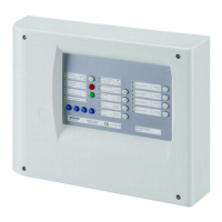
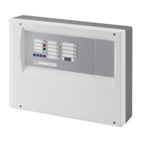
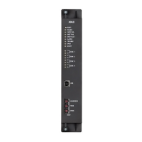
Fig. 10 Connections of the XCM1001-2 upper main board
XC10 provides EN54-2 option with requirements “Total loss of power”. This option
is mainly mandatory in France. When selected, “System fault” led and buzzer is
activated continuously for at least 1 hour after low discharge battery switch off (in
case the battery voltage fails below 21 V).
This option can be selected by wiring the +BAT terminal to the positive voltage of
batteries (use of remaining power of the battery).

 Loading...


